Method and device for controlling fan speed

A fan speed, fan technology, applied in the direction of using electric mode for temperature control, etc., can solve problems such as weak function, achieve the effect of strengthening function, improving reliability and life, and reducing resonance

Active Publication Date: 2014-11-05
南通东湖国际商务服务有限公司
View PDF4 Cites 0 Cited by
  • Summary
  • Abstract
  • Description
  • Claims
  • Application Information

AI Technical Summary

Problems solved by technology

It can be seen that the scheme for controlling the fan speed in the prior art has weak functions

Method used


Image

  • Method and device for controlling fan speed
  • Method and device for controlling fan speed

Examples


Embodiment Construction

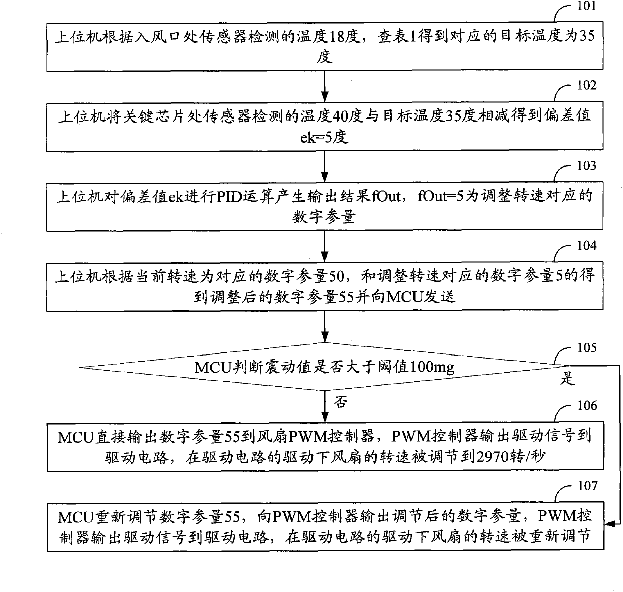
[0013] The specific implementation manners of a fan speed control method and device will be described below with reference to the drawings and embodiments.

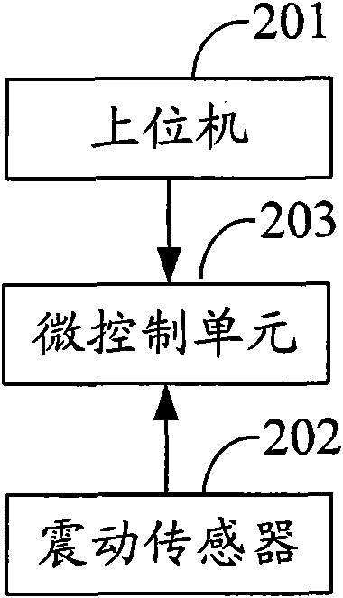
[0014] First, the hardware of the device in this embodiment is described. The device includes a fan, a vibration sensitive device, a vibration sensor, a temperature sensitive device, a temperature sensor, a host computer and an MCU (Micro Control Unit, Micro Control Unit). Temperature sensitive devices such as key chips of the equipment and PCB (Printed circuit board, Printed circuit board) are equipped with temperature sensors near them. The temperature sensor at the air inlet is used to detect the ambient temperature of the equipment. Used to detect the temperature of temperature sensitive devices. Vibration sensors such as acceleration sensors based on MEMS technology are arranged near vibration-sensitive devices such as hard disks (such sensors are generally micro-mechanical structures, packaged with signal conditioni...


PUM


Abstract

The invention discloses a method and a device for controlling fan speed, which aims at solving the problem of weak functions of the scheme of fan speed control in the prior art. The method comprises the following steps: controlling the fan speed, detecting vibration amplitude of vibration-sensitive units in the device, and readjusting the fan speed based on the current fan speed if the detected vibration amplitude is greater than the threshold in the process of controlling the fan speed. The control on the fan speed based on vibration detection reduces the possibility of generating resonance. Thereby, the invention has the advantages that the functions are enhanced as compared with the prior art.

Description

technical field [0001] The invention belongs to the technical field of automatic control, and is especially suitable for a fan speed control method and equipment. Background technique [0002] As people's requirements for various communication services are getting higher and higher, the functions of telecommunication equipment are getting stronger and stronger, and the power consumption is increasing sharply, which makes the problem of heat dissipation of the equipment more and more serious. Most equipment needs to be equipped with air-cooled heat dissipation devices. And the heat dissipation design of the equipment usually has greater redundancy. The price of having sufficient redundancy is to use a higher fan speed and a large number of fans. In practical applications, various devices need to adjust the fan speed according to different working conditions to achieve the purpose of heat dissipation. At present, the common method in the industry to control fan speed and heat...

Claims


Application Information

Patent Timeline
Patent Type & Authority Patents(China)
IPC IPC(8): G05D23/19
Inventor 王勇常辉邹鹏王侃
Owner 南通东湖国际商务服务有限公司
Why Eureka
Try Eureka