Unlock instant, AI-driven research and patent intelligence for your innovation.
Vehicle speed measurement method, supervisory computer and vehicle speed measurement system
What is Al technical title?
Al technical title is built by PatSnap Al team. It summarizes the technical point description of the patent document.
A measuring method, technology of monitoring machine
Active Publication Date: 2010-11-03
HANGZHOU HIKVISION DIGITAL TECH
View PDF0 Cites 39 Cited by
Summary
Abstract
Description
Claims
Application Information
AI Technical Summary
This helps you quickly interpret patents by identifying the three key elements:
Problems solved by technology
Method used
Benefits of technology
Problems solved by technology
There are many cameras used in binocular and multi-eye cameras, the installation is troublesome, and stereo matching is difficult
Based on the combination of panoramic cameras and close-up cameras, there are also shortcomings such as many cameras and complex installation requirements.
Method used
Image
Click on the blue label to locate the original text in one second.
Reading with bidirectional positioning of images and text.
Examples
Embodiment 1
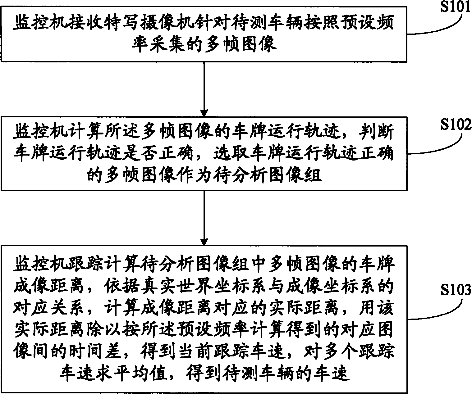
[0065] see figure 1 , a method for measuring vehicle speed provided by an embodiment of the present invention, comprising the following steps:
[0066] Step S101: The monitoring machine receives multiple frames of images collected by the close-up camera according to a preset frequency for the vehicle under test.
[0067] Because the time for the vehicle to pass through the field of view is very short, generally less than 1 second, in order to ensure real-time requirements, preferably, the close-up camera collects 25 frames of images per second, and requires that the frame intervals of the close-up camera image collection be as equal as possible, so that Used to evaluate the time spent in terms of the number of frames the vehicle passes by.
[0068] Step S102: The monitoring computer calculates the running track of the license plate of the multi-frame images, judges whether the running track of the license plate is correct, and selects the multi-frame images with the correct r...
Embodiment 2
[0132] see Figure 4 , a monitoring machine provided by an embodiment of the present invention, used for vehicle speed measurement, including:
[0133] Receiving module 401: used to receive multi-frame images collected by the close-up camera according to a preset frequency for the vehicle to be tested;
[0134] Image selection module 402: used to calculate the license plate running trajectory of the multi-frame images, determine whether the license plate running trajectory is correct, and select the correct multi-frame images of the license plate running trajectory as the image group to be analyzed;
[0135]Vehicle speed calculation module 403: used to track and calculate the license plate imaging distance of multiple frames of images in the image group to be analyzed, calculate the actual distance corresponding to the imaging distance according to the corresponding relationship between the real world coordinate system and the imaging coordinate system, and use the actual dist...
Embodiment 3
[0146] see Figure 5 , a vehicle speed measurement system provided in an embodiment of the present invention, comprising: a close-up camera 501, a supplementary light source 502, and the monitoring machine 503 described in the above embodiment,
[0147] The optical axis of the close-up camera 501 is facing the running route of the vehicle to be tested, and images are collected according to a preset frequency and sent to the monitoring machine 503;
[0148] The supplementary light source 502 is used to supplement light brightness for the close-up camera 501 when the light is insufficient;
[0149] The monitoring machine 503 is used to calculate the license plate track of the multi-frame images sent by the close-up camera 501, judge whether the license plate track is correct, and select the correct multi-frame images of the license plate track as the image group to be analyzed; track and calculate the track to be analyzed. Analyzing the license plate imaging distance of multipl...
PUM
Abstract
The invention discloses a vehicle speed measurement method, a supervisory computer and a vehicle speed measurementsystem. The method comprises the following steps of: receiving multiframe images collected by a close-up camera aiming at a vehicle to be tested according to a preset frequency by the supervisory computer; calculating the running track of a licence plate, and selecting the multiframe image with correct track as an image group to be analyzed; and tracking and calculating the imaging distance of the licence plate in the image group to be analyzed, calculating the actual distance corresponding to the imaging distance according to the correspondence between a real world coordinate system and an imaging coordinate system, dividing the actual distance by the time difference of the corresponding image obtained by calculating according to the preset frequency to obtain the current tracking vehicle speed, and averaging to obtain the vehicle speed of the vehicle to be tested. The supervisory computer comprises a receiving module, an image selecting module and a speed calculating module. The system comprises the close-up camera, a supplementary light source and the supervisory computer. The invention needs no extra vehicle speed detection equipment or a plurality of cameras for matching, has convenient installation, simple equipment and more flexible and various application scenes, and has the advantages of strong robustness and high speed measurement precision.
Description
technical field [0001] The invention relates to the field of automatic control, in particular to a vehicle speed measurement method, a monitoring machine and a vehicle speed measurement system. Background technique [0002] Speed measurement is an important means of traffic law enforcement. The current speed measurement methods mainly include the speed measurement method using auxiliary equipment and the speed measurement method based on video technology. [0003] The speed measurement methods using auxiliary equipment mainly include radar speed measurement and ground induction coil speed measurement. In speed measurement, auxiliary equipment such as laser, radar or ground induction coil are respectively required. During the measurement, vehicles are easy to interfere with each other and cause confusion, and Due to the limitation of auxiliary equipment, the data collection is not flexible enough. [0004] According to the principle of vision technology, it is divided int...
Claims
Application Information
Patent Timeline
Application Date:The date an application was filed.
Publication Date:The date a patent or application was officially published.
First Publication Date:The earliest publication date of a patent with the same application number.
Issue Date:Publication date of the patent grant document.
PCT Entry Date:The Entry date of PCT National Phase.
Estimated Expiry Date:The statutory expiry date of a patent right according to the Patent Law, and it is the longest term of protection that the patent right can achieve without the termination of the patent right due to other reasons(Term extension factor has been taken into account ).
Invalid Date:Actual expiry date is based on effective date or publication date of legal transaction data of invalid patent.
