Tenon engraving machine

A tenon engraving machine and engraving machine technology, applied in the field of engraving machines, to achieve the effect of reducing labor production costs, reducing costs, and increasing speed

Inactive Publication Date: 2010-11-10
李尚民
View PDF0 Cites 4 Cited by
  • Summary
  • Abstract
  • Description
  • Claims
  • Application Information

AI Technical Summary

Problems solved by technology

[0003] Through the above structure, it is indeed possible to effectively process the three-dimensional patterns on the wooden plate, but due to the limitation of the shape of the engraving machine and the structure of the hanger, the hanger can only move to the edge of the rectangular machine, that is, the cutting tool can The range of cutting can only reach the edge of the machine table. As a result, the structure of the above-mentioned engraving machine can only engrave three-dimensional patterns. For the tenon joints commonly used in woodworking furniture, semi-manual methods must still be used. processing, there is still room for improvement in efficiency

Method used


Image

  • Tenon engraving machine
  • Tenon engraving machine
  • Tenon engraving machine

Examples


Embodiment Construction

[0023] The above and other technical features and advantages of the present invention will be described in more detail below in conjunction with the accompanying drawings.

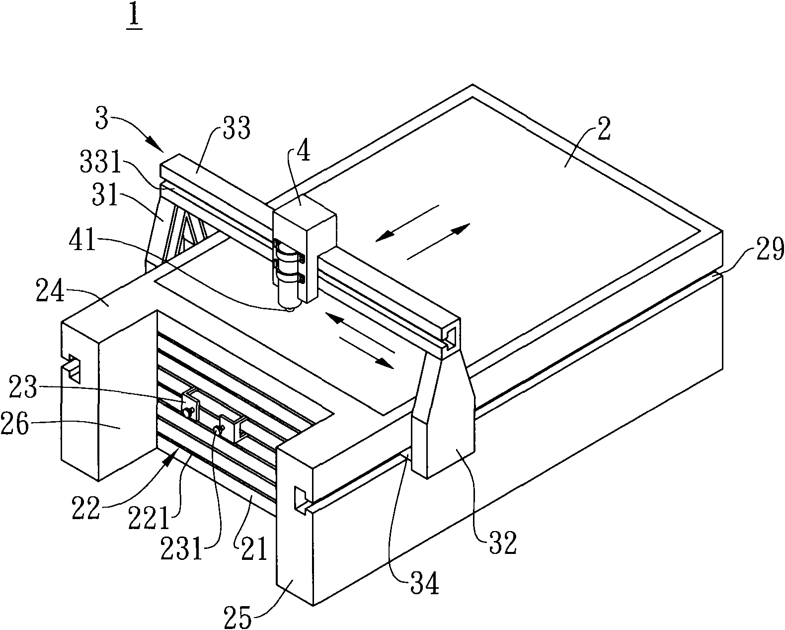
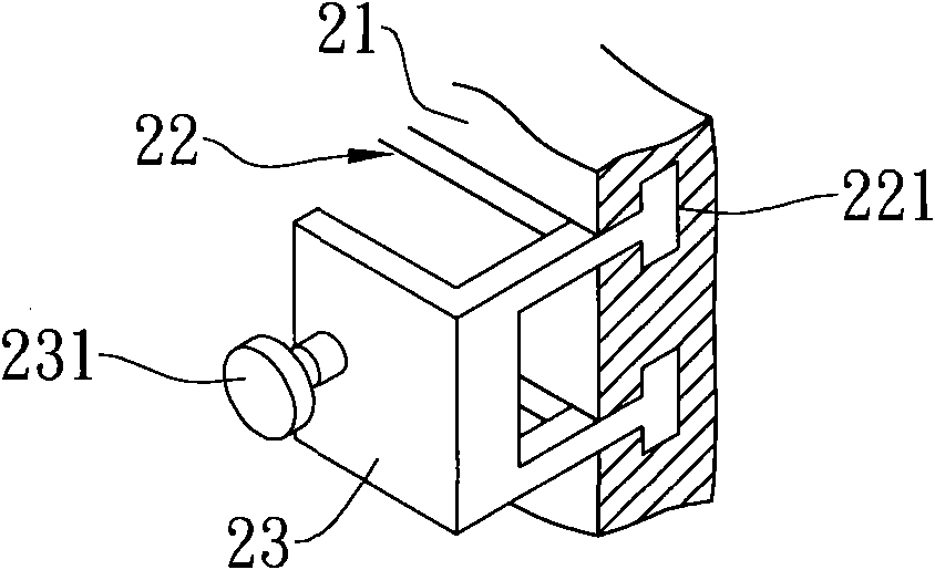
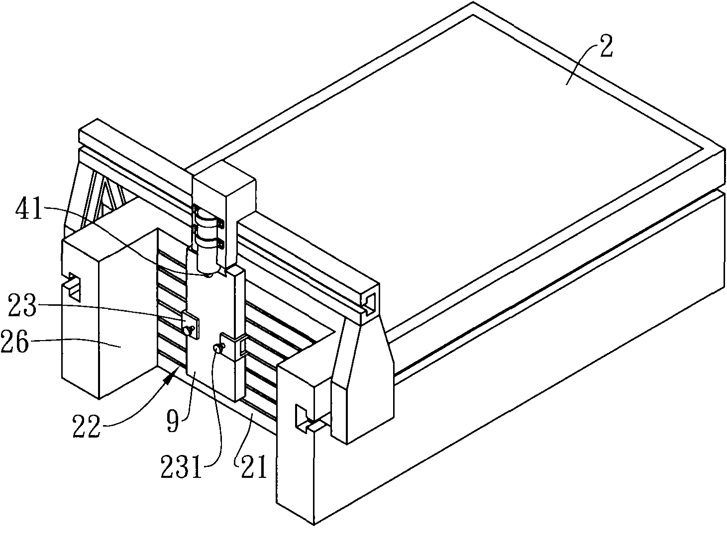
[0024] see figure 1 , 2 As shown, it is the first embodiment of the tenon engraving machine 1 of the present invention, which includes a machine table 2 , a hanger 3 and a knife seat 4 . The machine platform 2 is roughly cuboid, and its left and right sides are respectively provided with a long guide rail 29; Composed of rods 33, a roller 34 is respectively arranged on the relative inner side of the left bracket 31 and the right bracket 32, and the two rollers 34 are respectively positioned in the guide rails 29 on the left and right sides of the machine platform 2, so that the hanger 3 can move forward and backward in parallel with respect to the machine table 2; and a cutting tool 41 for cutting is provided below the tool seat 4, and the tool seat 4 is connected to the bridge rod 33 of the hanger 3, G...


PUM


Abstract

The invention relates to a tenon engraving machine. A left convex part is arranged at the left side of the front end surface of a stand, a right convex part corresponding to the left convex part is arranged at the right side of the front end surface of the stand, and a groove is formed among the front end surface, the left convex part and the right convex part of the stand; the front end surface of the stand is provided with a positioning part; and in addition, an inverted U-shaped hanging bracket which can move back and forth and oppositely parallel to the stand is arranged on the stand, a cutter seat which can slide left and right opposite to the hanging bracket is arranged on the hanging bracket, and a cutter is arranged below the cutter seat. Thus, when an article to be processed is located on the positioning part at the front end of the stand, a tenon joint on the article to be processed can be cut by moving the cutter.

Description

technical field [0001] The invention relates to an engraving machine, in particular to a tenon engraving machine capable of performing tenon joint cutting on objects to be processed. Background technique [0002] In order to meet the needs of mass production and save labor costs, the previous method of manually engraving three-dimensional patterns on wooden plates has been gradually replaced by a large number of flat three-dimensional engraving machines. And the generally used engraving machine mainly comprises a rectangular machine platform, an inverted U-shaped hanger and a knife seat, and the both sides of the said machine platform are respectively provided with a track, and the two ends of the hanger are respectively provided with a slide rail or a roller, with The hanger can move horizontally relative to the machine table, while the tool holder is connected to the hanger and can slide relative to the hanger. Thus, when the wooden flat plate is fixed on the machine tabl...

Claims


Application Information

Patent Timeline
Patent Type & Authority Applications(China)
IPC IPC(8): B27F1/08B44B3/02B44B3/06
Inventor 李尚民
Owner 李尚民
Why Eureka
Try Eureka