
Dry powder pump

A dry powder pump and bottle technology, applied in the direction of powder material distribution, unloading device, etc., can solve the problems that dry powder products cannot be directly applied, the structure cannot meet the requirements of dry powder, powder atomization and spraying can not be achieved, and the structure is reasonable Practical, easy to operate and use, and good sealing performance

Active Publication Date: 2010-11-10
ZHEJIANG JM IND
View PDF0 Cites 17 Cited by
  • Summary
  • Abstract
  • Description
  • Claims
  • Application Information

AI Technical Summary

Problems solved by technology

[0002] In traditional habits, sprayers have been widely applied to the packaging and use of liquid products, such as spray cans, foam pumps, and vacuum pumps, but for dry powder products such as prickly heat powder, talcum powder, and even pigment powder. Good packaging and usage methods, they are usually packed in cans or boxes, which are inconvenient to use and need to be used with other tools such as spoons or powder dusters. Moreover, during use, things often happen due to knocking over, causing dry powder to spill All over the place, it pollutes the environment and causes waste. People are eager for a new sprayer-like product suitable for the packaging and use of dry powder products
[0003] Although there are many sprayer structures produced by using the vacuum principle, such as spray cans, foam pumps, vacuum pumps, etc., they are only suitable for liquid products, and cannot meet the requirements of dry powder in structure, and cannot atomize the powder from the container. Therefore, It cannot be directly applied to dry powder products, and the structure needs to be improved.

Method used


Image

  • Dry powder pump
  • Dry powder pump
  • Dry powder pump

Examples


Embodiment Construction

[0042] The present invention will be further described in detail below in conjunction with the accompanying drawings and embodiments.

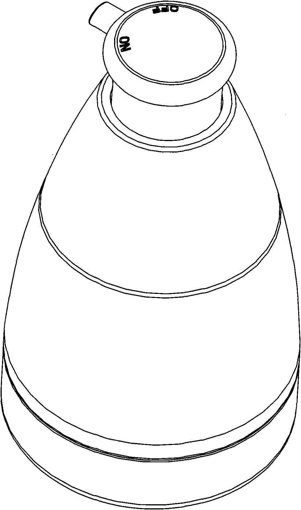
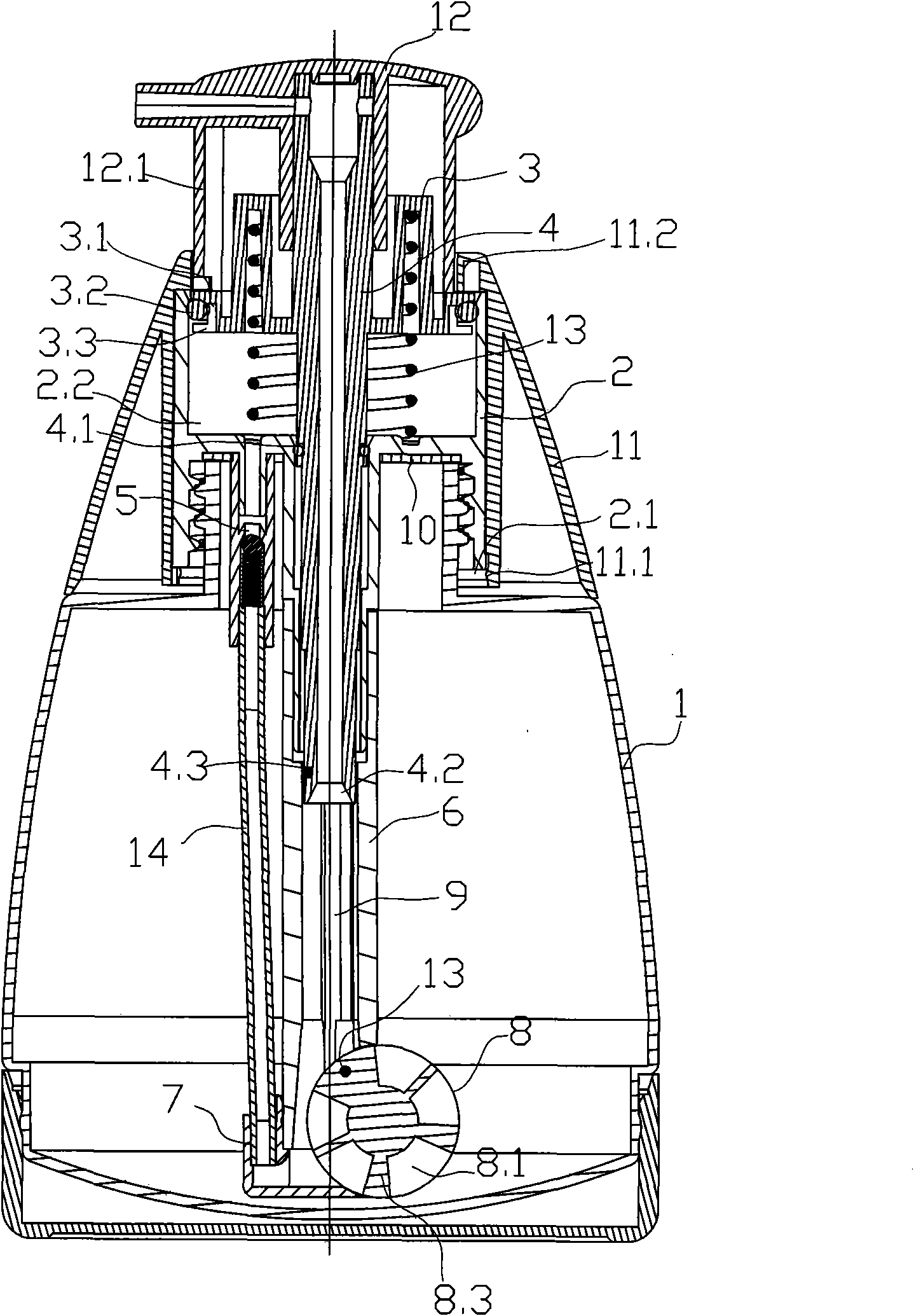
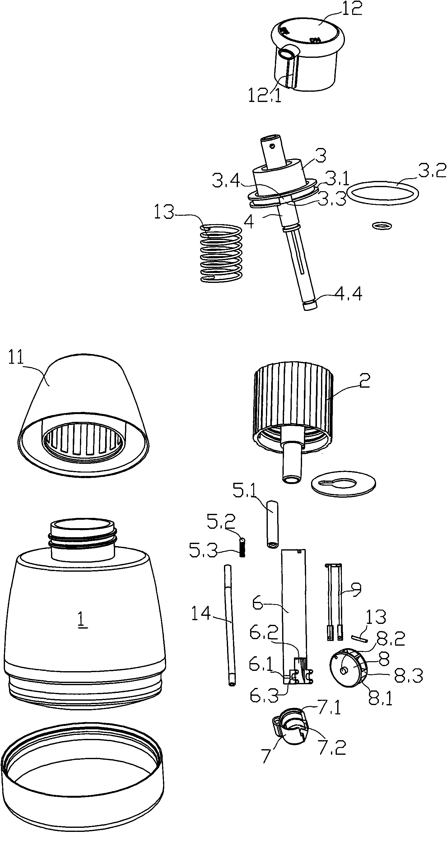
[0043] Implement Example 1, such as Figure 1-3Shown is a dry powder pump, which includes a bottle body 1, a cover 2, a piston 3, an elastic element, a piston rod 4, a one-way valve 5, a gear seat 6, a housing seat 7, a gear 8, a gear connecting rod 9, etc. The main parts, the bottle body 1 is hollow, and its inner cavity is used to hold powder such as talcum powder or prickly heat powder. Generally, the bottle body cannot hold all the powder, and some space needs to be reserved. In order to facilitate the dry powder in the bottle to be used up as much as possible, The bottom of the bottle body 1 is in a concave arc shape, the bottom of the bottle body 1 is socketed on the base of the bottle body, the cap 2 is installed on the upper part of the bottle body 1 through threaded connection, and a sealing ring 10 is lined between the cap 2 and the ...


PUM


Abstract

The invention relates to a dry powder pump comprising a bottle body, a cap, a piston and an elastic element, wherein an inner cavity of the bottle body is used for containing powder; the cap is connected to a mouth of the bottle body to form a piston cavity; the piston is driven to slide up and down by a head cap and then is limited and installed in the piston cavity to form an air compressing mechanism; and the elastic element makes the piston have a resetting trend. The dry powder pump is characterized in that a one-way valve is arranged in the mouth of the bottle body, an air inlet and the one-way valve is communicated with the piston cavity, and an air outlet of the one-way valve is communicated with the inner cavity of the bottle body; and the upper end of a hollow pipeline is communicated with a nozzle on the head cap, and the lower end of the hollow pipeline passes through the mouth of the bottle body to extend nearby the bottom of the bottle body and is directly or indirectly communicated with the inner cavity of the bottle body. The dry powder pump has the advantages of reasonable and practical structure, favorable sealing performance, convenient operation and use, light weight and convenient carrying and is easy to spray mixed powder and air.

Description

technical field [0001] The invention relates to a dry powder pump which sprays out the powder contained in it, which is similar to a liquid spray gun. It can be used to hold various powders such as talcum powder, prickly heat powder, and cosmetic powder in civil use. It can also be used in industry. It is used to hold various powders such as dyeing powder. Background technique [0002] In traditional habits, sprayers have been widely applied to the packaging and use of liquid products, such as spray cans, foam pumps, and vacuum pumps, but for dry powder products such as prickly heat powder, talcum powder, and even pigment powder. Good packaging and usage methods, they are usually packed in cans or boxes, which are inconvenient to use and need to be used with other tools such as spoons or powder dusters. Moreover, during use, things often happen due to knocking over, causing dry powder to spill All over the world, it pollutes the environment and causes waste. People are eage...

Claims


Application Information

Patent Timeline
Patent Type & Authority Applications(China)
IPC IPC(8): B65D83/06B65D25/40
Inventor 屠旭峰
Owner ZHEJIANG JM IND
Learn More