Milling and planing system

A milling and cutting tool technology, which is applied to earth moving machines/shovels, irrigation pipes, applications, etc., can solve the problems of poor construction quality, fast tool wear, low efficiency, etc., to improve construction efficiency, fast cutting speed, The effect of reducing the failure rate

Inactive Publication Date: 2010-11-10
北京华洋建设开发有限公司
View PDF9 Cites 1 Cited by
  • Summary
  • Abstract
  • Description
  • Claims
  • Application Information

AI Technical Summary

Problems solved by technology

[0003] The purpose of this invention is to provide an efficient milling system to solve the problem

Method used


Image

  • Milling and planing system
  • Milling and planing system
  • Milling and planing system

Examples


Embodiment Construction

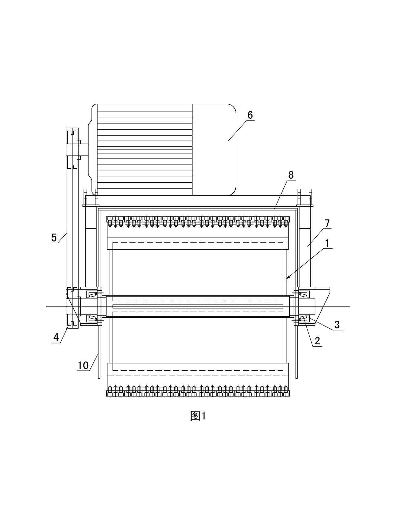
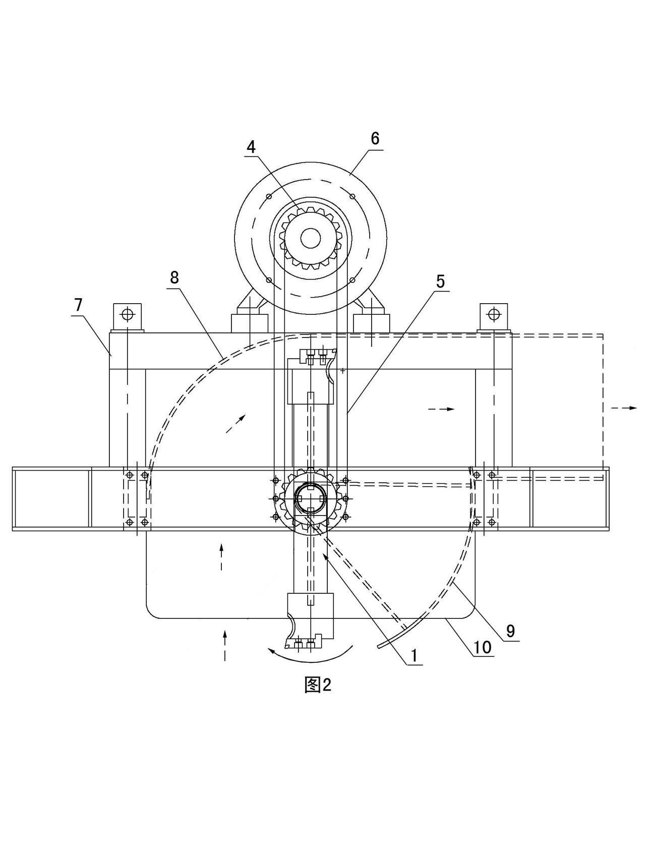
[0023] Examples see figure 1 , figure 2 As shown, this milling system includes a cutter rotor assembly frame 7, a motor 6 fixedly connected to the cutter rotor assembly frame 7, and a cutter rotor assembly 1 rotatably connected to the cutter rotor assembly frame 7. , wherein the output end of the motor 6 drives and connects the tool rotor assembly 1 . The motor 6 can be installed on the upper end or the side end of the cutter rotor assembly structural frame 7, and the present embodiment is installed on the upper end of the cutter rotor assembly structural frame 7.

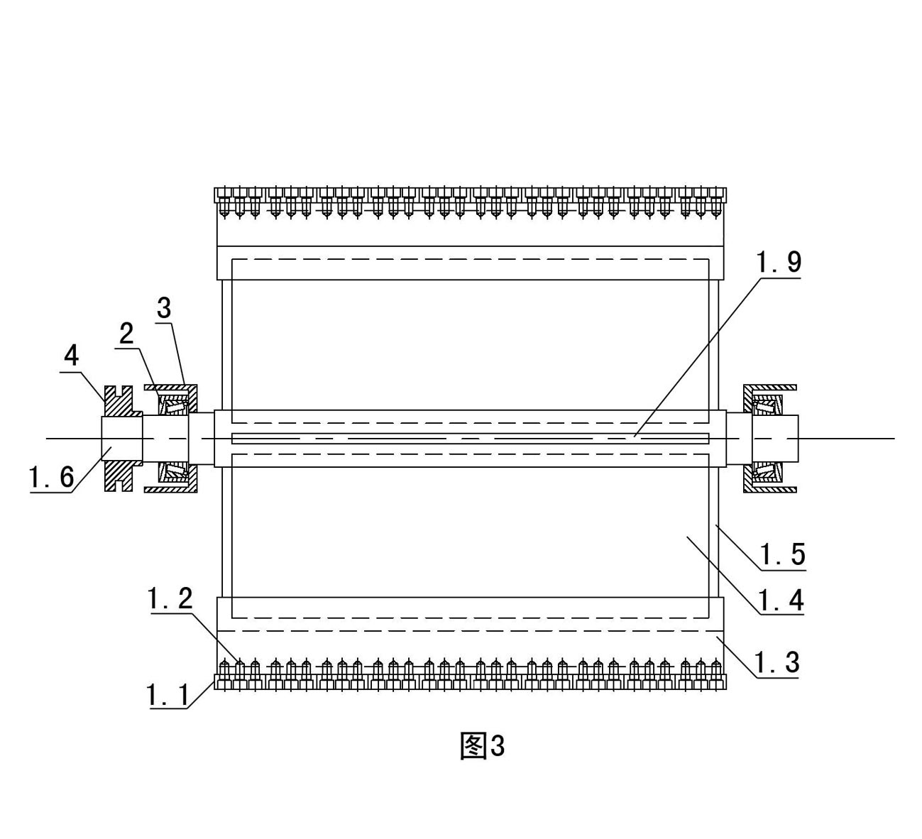
[0024] see figure 2 , image 3 , the cutter rotor assembly 1 is composed of a cutter 1.1, a bolt 1.2, a cutter seat 1.3, a connecting plate 1.4, a reinforcing plate 1.5 and a transmission shaft 1.6, wherein the transmission shaft 1.6 is rotationally connected to the cutter rotor assembly through a bearing 2 and a tile box 3 On the structural frame 7, there are at least two connecting plates 1.4 and they are e...


PUM


Abstract

The invention discloses a milling and planning system, which comprises a cutter rotor assembly structure frame, a motor fixedly connected on the cutter rotor assembly structure frame and a cutter rotor assembly rotationally connected on the cutter rotor assembly structure frame, wherein the cutter rotor assembly consists of cutters, bolts, a cutter base, connecting plates, reinforcement plates and a transmission shaft; the transmission shaft is rotationally connected on the cutter rotor assembly structure frame through a bearing and a tile box; the number of the connecting plates is at least two, and the connecting plates are uniformly distributed along the radial direction of the transmission shaft; the bottom end of each connecting plate is fixedly connected with the transmission shaft, while the top end is fixedly connected with the cutter base; the reinforcement plates are positioned on two sides of the connecting plates and connected between the transmission shaft and the cutter base; and the cutters are arranged in one row and detachably connected on the cutter base through the bolts. The system greatly improves the construction efficacy of a flattening machine, reduces the fault rate of the flattening machine on the premise of ensuring the construction quality, and has the advantages of convenient maintenance, assembly and disassembly.

Description

technical field [0001] The invention relates to a milling device installed in a leveling machine. Background technique [0002] Before lining concrete on the slope and bottom of the channel, the base surface of the soil layer must be treated first to ensure that the soil layer is flat and meets the design requirements. Existing canals generally need to reserve a 300mm thick soil layer after mechanical or manual excavation. If manual slope repair and leveling are adopted, the efficiency is too low and the labor intensity is too high. Not only can it not meet the needs of large-area canal lining If the traditional leveling machinery is used for large-scale soil leveling work, there are also shortcomings such as high equipment failure rate, slow construction speed, and waste of manpower and material resources. Not only the construction effect, The construction quality is not ideal, and it will affect the construction progress and increase the construction cost. In addition, t...

Claims


Application Information

Patent Timeline
IPC IPC(8): E02F5/30E02B13/00
Inventor 杨永革翟利川
Owner 北京华洋建设开发有限公司
Why Eureka
Try Eureka