Electric cleaning brush

A cleaning brush and electric technology, applied in the direction of brushes, brush bodies, bristles, etc., can solve the problems of heavy workload, stuck brush head, motor damage, etc., achieve long service life, increase cleaning speed, and improve continuous use time Effect

Inactive Publication Date: 2010-11-17
宁波宏泰工具实业有限公司
View PDF4 Cites 6 Cited by
  • Summary
  • Abstract
  • Description
  • Claims
  • Application Information

AI Technical Summary

Problems solved by technology

[0002] In daily life, some grid-shaped trays, brackets and other items will accumulate more dirt after long-term use. Take the grill on the grill as an example, the grill is generally welded by multiple metal strips , After the grilled food is finished, there will be more oil stains on the grill, and its grid shape makes cleaning more difficult
Generally speaking, people use common brushes to clean the grill, and the workload is large and the speed is relatively slow. However, the electric brushes in the prior art, such as electric shoe brushes, the brush heads of the electric shoe brushes are formed by the brush head holder. It consists of a number of bristles, which are densely fixed on one side of the brush head holder and form a cylinder. The arrangement of the bristles is relatively compact and the ends of the bristles are on the same plane, and then the brush head holder is fixed on the output shaft of the motor. The bristles are parallel to the output shaft of the motor. The electric brush with this structure is only suitable for cleaning a continuous plane. For grid-shaped items, because the arrangement of the bristles is relatively compact and the ends of the bristles are on the same plane, the bristles are not easy to extend. In the gaps between the bars of grid-like items, the dirt in the gaps cannot be cleaned, and when the bristles are forced into the gaps, it is easy to cause damage to the bristles and the sticking of the brush head, and even damage to the motor. Electric brushes in the prior art are not suitable for cleaning grills and similar grid-like items

Method used


Image

  • Electric cleaning brush
  • Electric cleaning brush

Examples


Embodiment Construction

[0017] The present invention will be further described in detail below in conjunction with the accompanying drawings and specific embodiments.

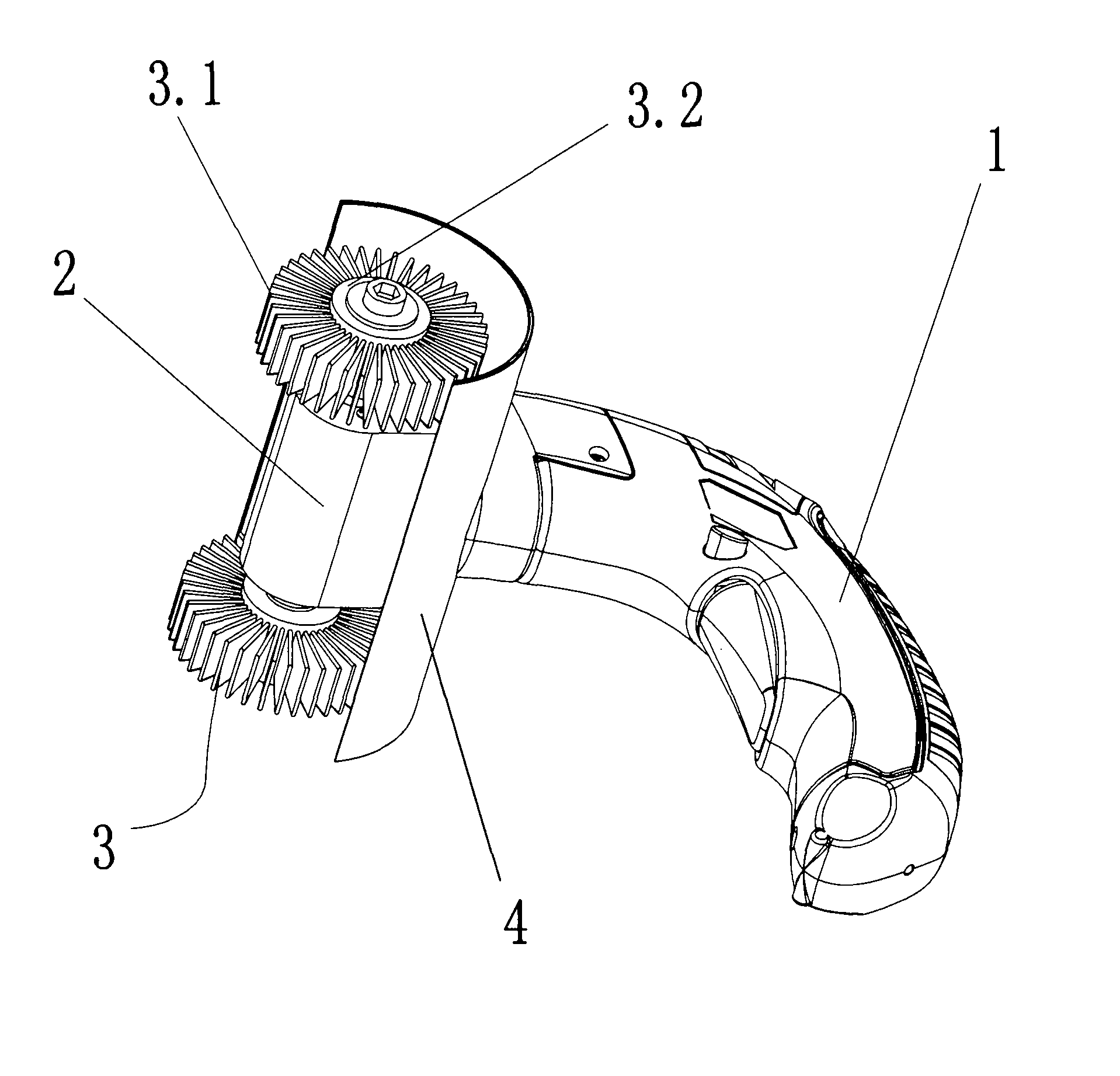
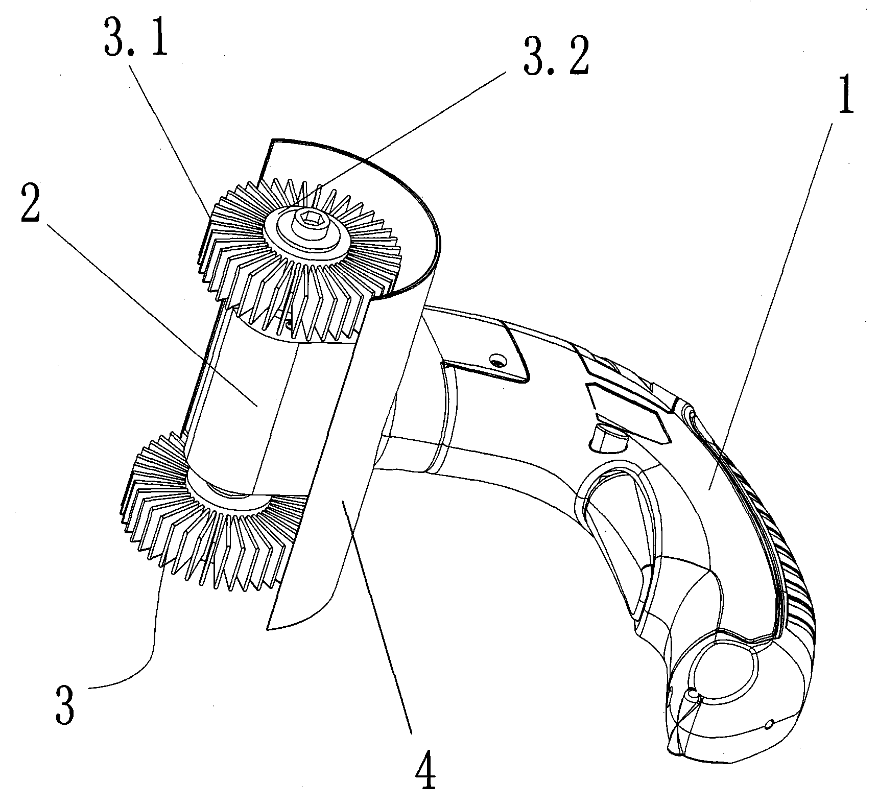
[0018] As shown in the accompanying drawings, the electric cleaning brush of the present invention includes a housing 1 used as a handle, a motor 2 mounted on the front end of the housing 1, a brush head 3 driven by the motor 2 and a power supply (not shown), the The brush head 3 is composed of bristles 3.1 and a brush head seat 3.2, and the brush head seat 3.2 is installed on the output shaft of the motor 2.

[0019] The bristles 3.1 of the present invention are distributed outwardly along the circumference of the brush head holder 3.2. A baffle 4 extending along the centerline of the brush head 3 is provided between the shell 1 and the brush head 3 , and the baffle 4 is fixed on the front end of the shell 1 . In order to make the cleaning effect better, the bristles 3.1 are preferably thin copper wires.

[0020] The motor 2 is a d...


PUM


Abstract

The invention relates to an electric cleaning brush comprising a casing used as a handle, a motor arranged at the front end of the casing, a brush head driven by a motor and a power supply, wherein the brush head consists of bristles and a brush head seat; the brush head seat is arranged on an output shaft of the motor; and the bristles are outward and divergently distributed along the circumferential direction of the brush head seat. The bristles are outward and divergently distributed on the periphery of the brush head seat, the end parts of the bristles are positioned on the same circumferential surface, a gap is reserved between adjacent bristles on the circumferential direction, the bristles are easy to extend into the gap between lattice bars and are difficult to lock, thereby being convenient to clean latticed articles. Therefore, the brush head moves along the neck direction of the circumferential surface formed by the bristles and is close to the lattice bars of the latticed articles when driven by the motor to rotate and the bristles brush past from the lattice bars, thereby cleaning dirt on the latticed bars.

Description

technical field [0001] The invention relates to an electric tool, in particular to an electric cleaning brush. Background technique [0002] In daily life, some grid-shaped trays, brackets and other items will accumulate more dirt after long-term use. Take the grill on the grill as an example, the grill is generally welded by multiple metal strips , After the grilled food is finished, there will be more oil stains on the grill, and its grid shape makes cleaning more difficult. Generally speaking, people use common brushes to clean the grill, and the workload is large and the speed is relatively slow. However, the electric brushes in the prior art, such as electric shoe brushes, the brush heads of the electric shoe brushes are formed by the brush head holder. It consists of a number of bristles, which are densely fixed on one side of the brush head holder and form a cylinder. The arrangement of the bristles is relatively compact and the ends of the bristles are on the same p...

Claims


Application Information

Patent Timeline
Patent Type & Authority Applications(China)
IPC IPC(8): A46B13/02A46B9/02A46B15/00
Inventor 董明宏
Owner 宁波宏泰工具实业有限公司
Why Eureka
Try Eureka