Dust collector with dust compression function

A dust collector and dust technology, applied in vacuum cleaners, household appliances, cleaning equipment, etc., can solve the problems of dust affecting installation, inhaling fine dust, inconvenience to users, etc. simple effect

Inactive Publication Date: 2010-11-17
LG ELECTRONICS (TIANJIN) APPLIANCES CO LTD
View PDF4 Cites 9 Cited by
  • Summary
  • Abstract
  • Description
  • Claims
  • Application Information

AI Technical Summary

Problems solved by technology

Not only is it easy to cause dust to fly when dumping dust, causing inconvenience to users, but also when the dust collection bucket cover is opened, the holding position is higher

Method used


Image

  • Dust collector with dust compression function
  • Dust collector with dust compression function
  • Dust collector with dust compression function

Examples


Embodiment Construction

[0025] Below in conjunction with accompanying drawing and specific embodiment the present invention is described in further detail:

[0026] The working principle of the vacuum cleaner of the present invention is the same as that of the prior art, and the prior art can be referred to, so it will not be described again, and the same symbols as those of the prior art will be used. The differences between the present invention and the prior art will be described below Detailed explanation:

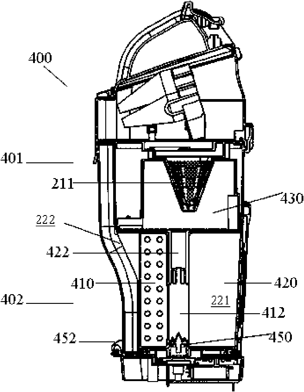
[0027] Such as image 3 As shown, the dust collecting bucket 202 includes a pair of pressing plates 410 and 420 , wherein the rotating compressing piece 410 is rotatably disposed in the dust collecting bucket 402 , and the fixed compressing piece 420 is fixed in the dust collecting bucket 402 . The upper end of the fixed compression piece 420 is fixedly connected with the lower surface of the partition plate 230 , and integrally formed with the stationary shaft 422 coaxial with the axis of t...


PUM


Abstract

The invention discloses a dust collector with a dust compression function. The dust collector comprises a dust separator and a dust collection barrel, wherein the dust collection barrel stores dust separated by using the dust separator; a rotary compression sheet is arranged in the dust collection barrel and is used for compressing the dust stored in a dust storage under an interaction effect of using and fixing the compression sheet; a driven gear used for driving is arranged on a chassis; one side of the chassis is connected with the bottom side of the dust collector by using a hinge structure; and the wall of the collector on the other corresponding side is provided with a locking device and a button device used for unlocking the locking device. By adopting a chassis tilting dust collector, dust emptying degree is high, operation is simple and an operation point is low, secondary pollution and unhappiness of a user caused by flying dust are avoided and convenience to reclose the chassis is brought.

Description

technical field [0001] The invention relates to a vacuum cleaner, in particular to a dust collector with dust compression function. Background technique [0002] In general, a vacuum cleaner is a device for sanitation that uses vacuum pressure generated by a vacuum motor installed in its body to suck dust-containing gas and then filters the dust in the gas. [0003] figure 1 It is a three-dimensional schematic diagram of a vacuum cleaner in the prior art. Such as figure 1 As shown, the vacuum cleaner includes a vacuum cleaner body 1 with a suction force generator therein, a dust collector for separating dust from the introduced air and storing the separated dust; The suction nozzle 9 passed through; and the electric wire 4 for power supply; the handle 3 and the roller 8 that allow the user to operate the vacuum cleaner; the connecting hose 5 that connects the suction nozzle 9 to the vacuum cleaner body 1, and the hose 5 fixed part 5a. One side of the main body 1 is fixe...

Claims


Application Information

Patent Timeline
IPC IPC(8): A47L9/00
Inventor 高岩
Owner LG ELECTRONICS (TIANJIN) APPLIANCES CO LTD
Why Eureka
Try Eureka