Prepuce cutting stitching instrument

A suturing device and foreskin technology, which is applied in the field of medical equipment, can solve the problems of increasing the number of surgical instruments, shortening the operation time, and not giving, etc., so as to reduce pain and improve the operation speed

Active Publication Date: 2010-11-17
常熟市亨利医疗器械有限公司
View PDF8 Cites 47 Cited by
  • Summary
  • Abstract
  • Description
  • Claims
  • Application Information

AI Technical Summary

Problems solved by technology

[0003] Utility model patent authorization announcement number CN2175578Y discloses a circumcision automatic suture device. The achievement of this patent is: compared with the surgical instrument of circumcision forceps provided by ZL9221721.3, it can realize multi-needle suture at one time, but this The patent does not give the technical inspiration for cutting the

Method used


Image

  • Prepuce cutting stitching instrument
  • Prepuce cutting stitching instrument
  • Prepuce cutting stitching instrument

Examples


Embodiment 1

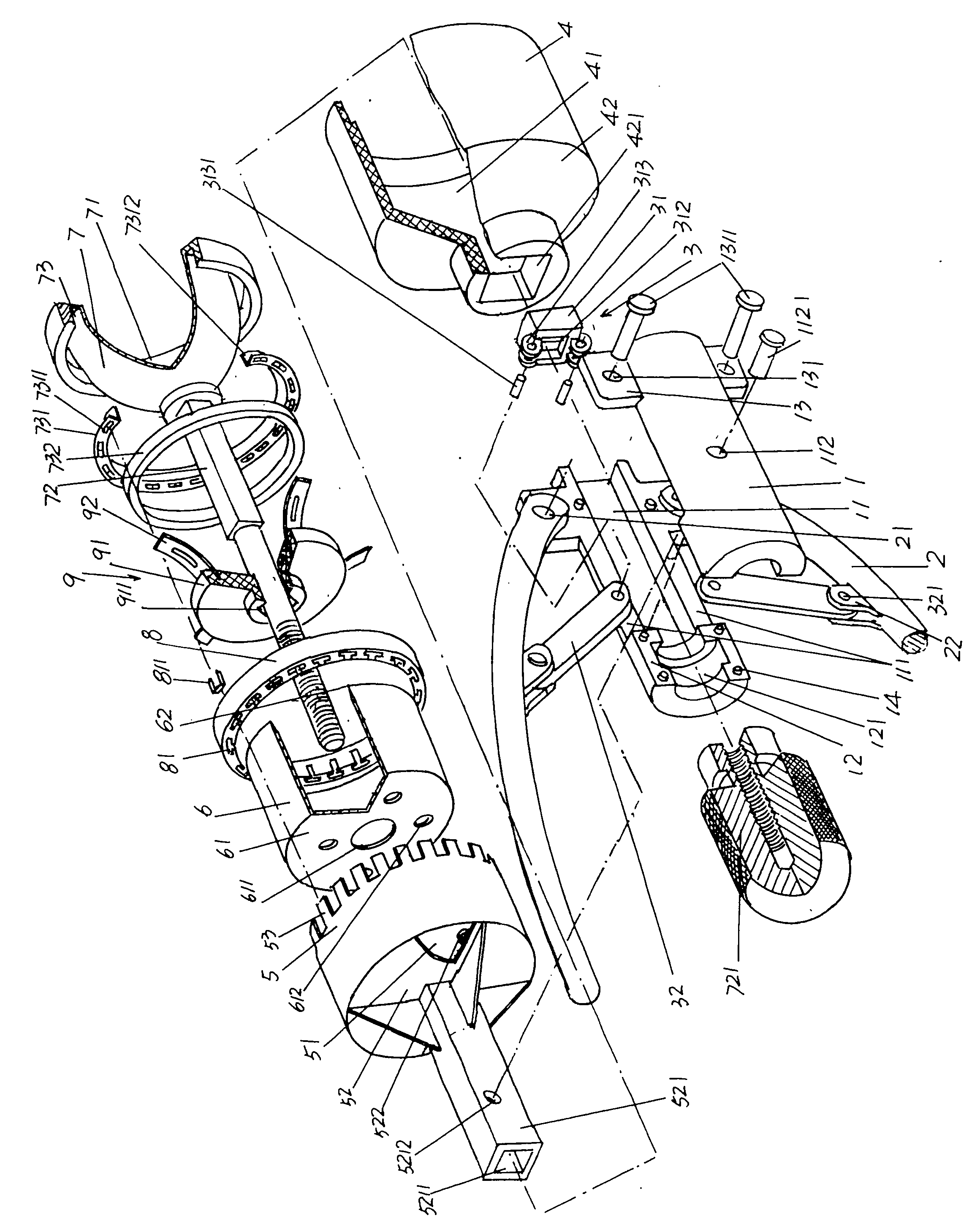
[0023] Please see figure 1 , a pair of handle shells 1 that are arranged face-to-face and combined into one body with the same shape and size as each other are given, as shown in the figure, in the back of a pair of handle shells 1 (with figure 1 The shown position state is taken as an example, the same below) a handle shell 1 extends toward the two ends of one side of the front handle shell 1, and there are tenons 14 (also called tenons or tenons) whose number is not limited by the number shown in the figure. Correspondingly, on the front handle shell 1 and at the position corresponding to the tenon 14, there are tenon holes equal in number to the tenon 14, so that the aforementioned tenon 14 can be tenoned into In the mortise and tenon hole, therefore, a pair of handles combine the shell valves 1 with each other to form a whole. A sliding chamber 11, a knob seat 12 and a handle hinge seat 13 are respectively formed on the opposite sides of a pair of handle shells 1, wherein...

Embodiment 2

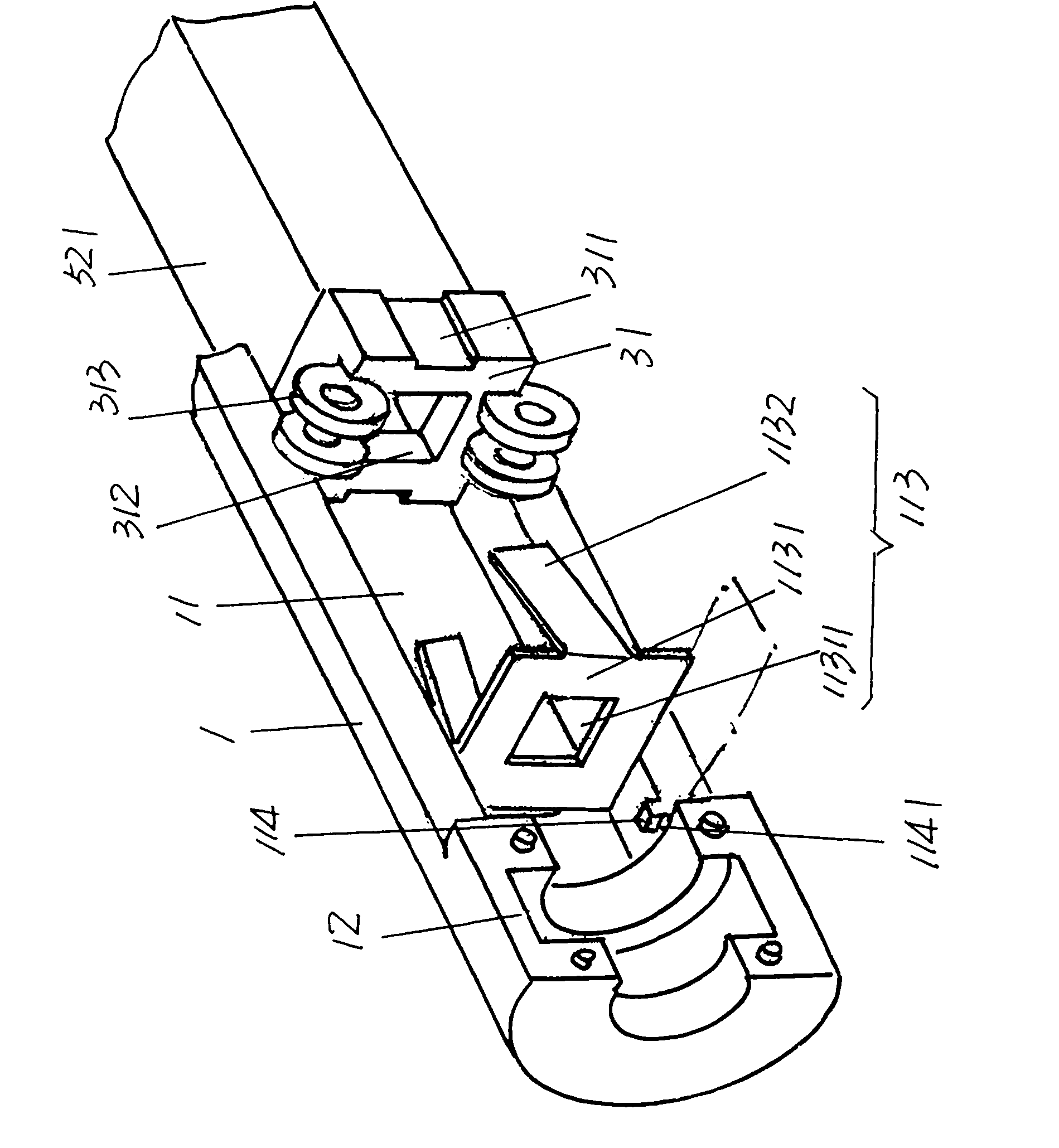
[0031] please see figure 2 In order to ensure the safety effect as a medical surgical instrument and avoid or eliminate the hidden danger of cross-infection, a reusable interference device 113 made of stainless steel is preferably embedded in the sliding cavity 11 of a pair of handle shell valves 1, in order to meet Repeating the setting of the interfering device 113, a positioning lug 114 extends on the corresponding two sides of each sliding cavity 11 of a pair of handlebar shell valves 1 towards the end of the knob seat 12. The pair of positioning lugs 114 correspond to each other, and the positioning lugs There is a reed body insertion gap 1141 between the edge 114 and the wall of the knob seat 12 . The aforementioned reusable interferometer 113 includes a reed body 1131 and a pair of reed feet 1132, and a reed slot 311 is respectively provided on the outer walls of the corresponding two sides of the guide sleeve 31, which is called the corresponding guide sleeve 31 here....


PUM


Abstract

The invention relates to a prepuce cutting stitching instrument, belonging to the technical field of medical instruments. The stitching instrument comprises a pair of hand valves, a pair of hand grips, a balance remover, a knife shell, a push-type broach disc, a bell-type cutting knife, a glans penis cap and a nail carrying container, wherein each hand valve is provided with a sliding cavity, a knob base and a pair of hand hinging bases; the hand grips are articulated with the hand hinging bases; the balance mover is connected with the hand grips; the knife shell is provided with a shell cavity and is fixed to the end faces of the hand valves; the push-type broach is provided with a cutting knife cavity, and a pushing knife shaft is extended from the center of the external side of the top wall of the push-type broach disc; the glans penis cap is provided with a glans penis cavity, a moving rod is fixed on the glans penis cap, the external wall of the base part of the glans penis cap is provided with a ring shaped groove, a clubfoot disc is inserted in the ring shaped groove, and the moving rod corresponds to the knob base and is matched with one adjusting knob; and the nail carrying container is arranged on the clubfoot disc. The invention has the advantages that the actions of cutting and stitching can be completed at a time, the speed of operation is increased, and the pain of patients can be alleviated.

Description

technical field [0001] The invention belongs to the technical field of medical devices, and in particular relates to a circumcision and stapler. Background technique [0002] About the technical information of circumcision device, in literature especially Chinese patent document, there are reports already, disclose a kind of circumcision cutter as utility model patent authorization announcement number CN2555783Y, and as publication number CN101301219A recommended a kind of titanium-nickel memory alloy foreskin Cutter also introduces a circumcision stapler as CN201365945Y. The common advantage of the above-mentioned patented technical solutions is that the structure is simple, but there are common deficiencies. First, they are not circumcision devices in the true sense, but belong to the category of lesion rings; Hold and control the strength of the strangulation, the probability of a successful one-time operation is relatively low; moreover, after the strangulation, the sur...

Claims


Application Information

Patent Timeline
IPC IPC(8): A61B17/326A61B17/068
CPCA61B17/326
Inventor 朱振荣朱佳孙朴
Owner 常熟市亨利医疗器械有限公司
Why Eureka
Try Eureka