
Steam sprayer

A sprayer and steam technology, which is applied in the direction of atomizers, bathing devices, physical therapy, etc. for treatment, can solve the problems of sprayer burst, user injury, and high cost, so as to improve the safety of use and reduce the placement of Space, the effect of reducing packaging costs

Inactive Publication Date: 2010-11-17
ZHUHAI JINDAO ELECTRIC APPLIANCE
View PDF5 Cites 6 Cited by
  • Summary
  • Abstract
  • Description
  • Claims
  • Application Information

AI Technical Summary

Problems solved by technology

[0002] Steam sprayer is one of the most commonly used beauty devices in the fields of beauty treatment, physical therapy and health care. Because the sprayer has better effects in beauty treatment and physical therapy and health care, it is widely used in various beauty care, physical therapy and health care institutions, and even many users set it up for beauty treatment. Spray is used as a home beauty, physical therapy and health care device. When the user uses the hot mist generated by the steam spray machine for beauty treatment or physical therapy and health care, the water pot inside the sprayer boils the water to generate water vapor, and the water vapor is sprayed on the human skin. The skin is attracted to achieve the effect of beauty treatment, physical therapy and health care. However, due to the imperfect technology of the existing steam sprayer, the water vapor generated by the heating of the inner kettle can only be sprayed out by itself under the pressure formed inside the kettle. The spray effect is poor and unstable. When the water vapor is sprayed out, the nozzle must be used, and the nozzle is also equipped with an inner tube to cooperate with the steam port of the kettle, so that the water vapor is sprayed from the steam port along the inner tube, and the spray tube In the process, in order to make the water vapor spray far, it is necessary to make the nozzle on the nozzle as small as possible to ensure that the water vapor can be sprayed for a longer distance. The smaller nozzle will cause the sprayer to be dangerous. The hot water may be sprayed out together with the mist along the inner tube, which is easy to cause harm to the user. In addition, once the small nozzle is blocked, the water vapor cannot be sprayed out, and the pressure inside the kettle will gradually increase, causing the sprayer to spray. There is a danger of bursting, which poses a safety threat to users; in addition, since existing steam spray machines need to use a nozzle for spraying, and the nozzle and the inner tube inside it are not removable, the longer nozzle will cause The sprayer occupies a large space when placed, and greatly increases the packaging cost and transportation cost of the product, which is not conducive to the popularization and use of the steam sprayer
[0003] In summary, the existing steam sprayers have the technical defects of poor spray effect, low safety and high cost

Method used


Image

  • Steam sprayer
  • Steam sprayer
  • Steam sprayer

Examples


Embodiment 1

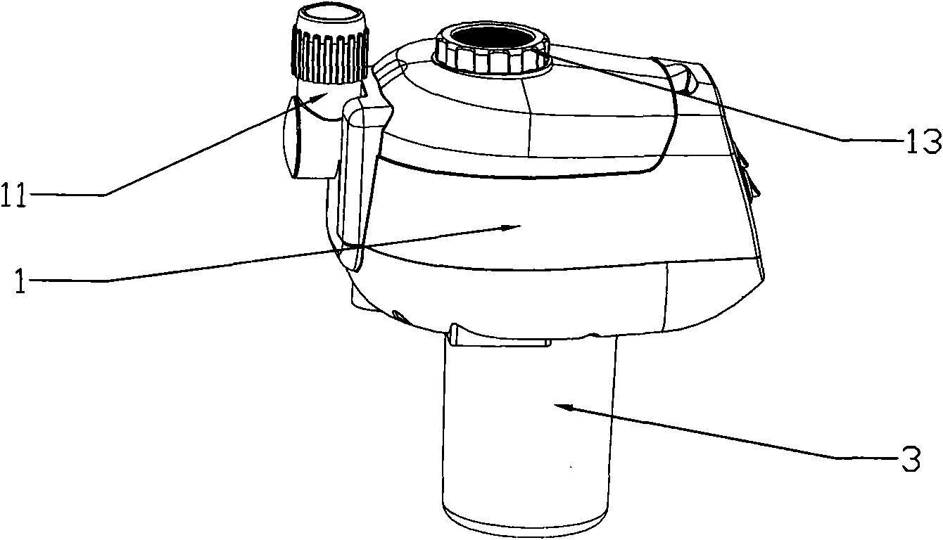
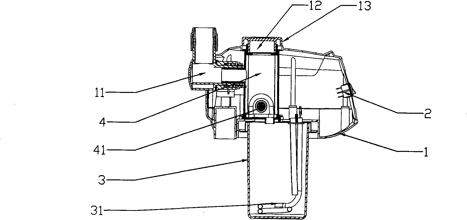
[0017] Such as figure 1 , figure 2 As shown, the present invention includes a housing 1, the housing 1 is provided with a spray port 11, the inside of the housing 1 is provided with a control panel 2, a kettle 3, and the control panel 2 is provided with several control switches, The water pot 3 is provided with a heating wire 31, and the heating wire 31 is electrically connected to the control board 2. The water pot 4 is filled with water, which is heated by the heating wire 31 to generate water vapor. 1 is also provided with an air duct 4, the air duct 4 communicates with the kettle 3 and the spray port 11 respectively, and the side wall of the air duct 4 is provided with a spray fan 41, and the spray fan 41 is connected to the spray port 11. The control board 2 is electrically connected. During use, the heating wire 31 and the spray fan 41 in the water pot 3 are energized through the control board 2, and the heating wire 31 in the water pot 3 is first controlled by the co...

Embodiment 2

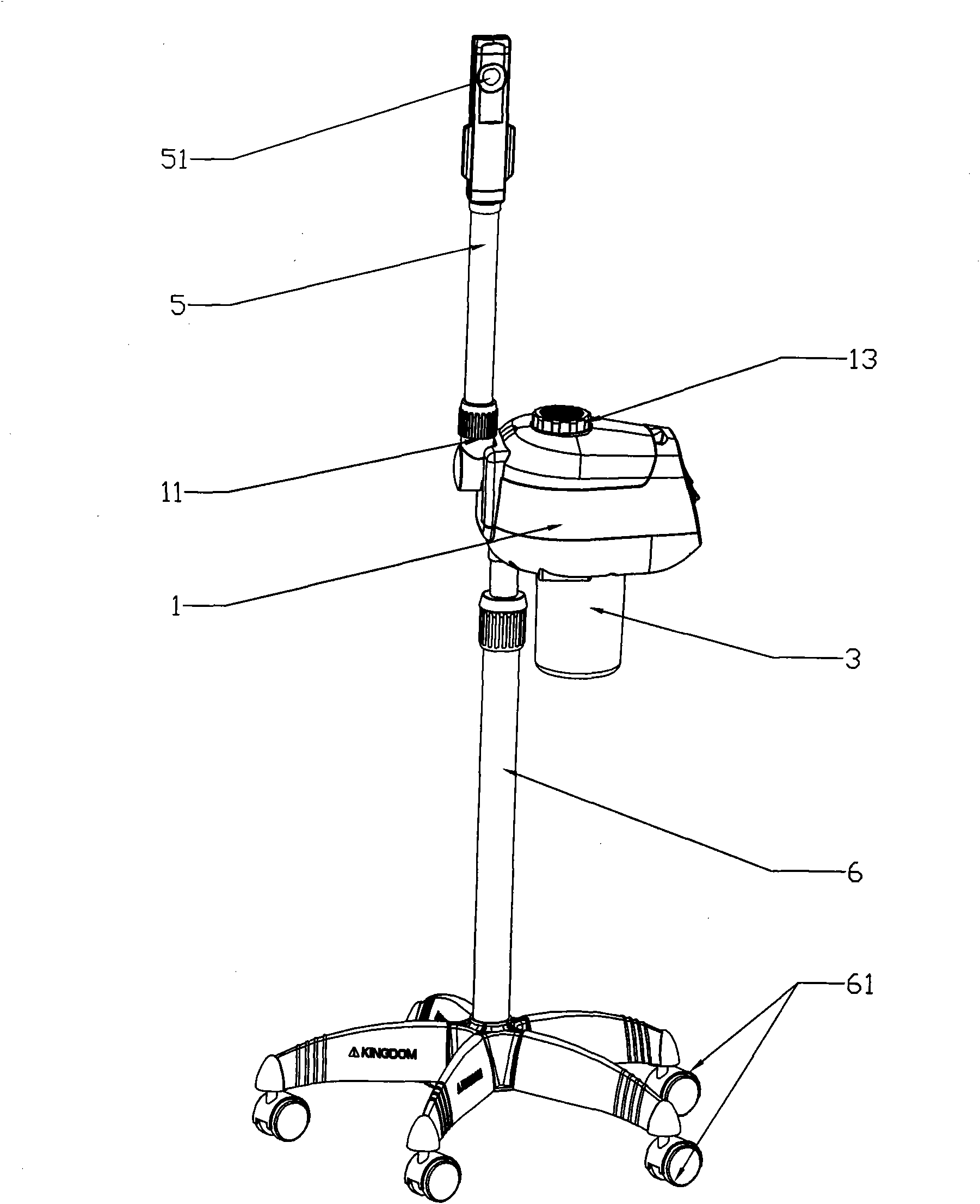
[0019] Such as image 3 , Figure 4 , Figure 5 As shown, compared with Embodiment 1, this embodiment also includes a spray tube 5, one end of the spray tube 5 is rotatably engaged with the spray port 11, and the other end of the spray tube 5 is provided with a spray head 51, The spray pipe 5 is detachably matched with the spray port 11 of the housing 1. When the sprayer needs to be used at a relatively long distance, the spray pipe 5 can be installed for use. When in use, the air duct 4 The mist in the interior is pushed by the spray fan 41 and enters the inside of the spray pipe 5 from the spray port 11, and then sprays out from the spray head 51 of the spray pipe 5, and the spray pipe 5 can also be in contact with the spray The matching part of the mouth 11 is rotated to select a suitable angle for use, which is convenient and flexible; as in the short-distance use or non-use state, the spray pipe 5 can be removed to reduce the occupied space and facilitate placement.

...


PUM


Abstract

The invention discloses a steam sprayer, and aims to provide the steam sprayer with a good spraying effect, high safety and low cost. The steam sprayer comprises a shell (1), wherein the shell (1) is provided with a spray port (11); a control board (2) and a kettle (3) are arranged in the shell (1); an electric heating wire (31) is arranged in the kettle (3) and electrically connected with the control board (2); an air duct (4) is also formed in the shell (1) and communicated with the kettle (3) and the spray port (11) respectively; the side wall of the air duct (4) is provided with a spraying fan (41); the spraying fan (41) is electrically connected with the control board (2); and the fog produced by the kettle (3) is sprayed out from the spray port (11) by using the power provided by the spraying fan (41). The steam sprayer can be widely applied to the fields such as cosmetology, aroma therapy, health care and the like.

Description

technical field [0001] The invention relates to a steam spray machine. Background technique [0002] Steam sprayer is one of the most commonly used beauty devices in the fields of beauty treatment, physical therapy and health care. Because the sprayer has better effects in beauty treatment and physical therapy and health care, it is widely used in various beauty care, physical therapy and health care institutions, and even many users set it up for beauty treatment. Spray is used as a home beauty, physical therapy and health care device. When the user uses the hot mist generated by the steam spray machine for beauty treatment or physical therapy and health care, the water pot inside the sprayer boils the water to generate water vapor, and the water vapor is sprayed on the human skin. The skin is attracted to achieve the effect of beauty treatment, physical therapy and health care. However, due to the imperfect technology of the existing steam sprayer, the water vapor generate...

Claims


Application Information

Patent Timeline
IPC IPC(8): A61H33/06A61M11/00
Inventor 贺晓东
Owner ZHUHAI JINDAO ELECTRIC APPLIANCE
Learn More