Automatic axial turnover mechanism for fixtures

A turning mechanism and automatic technology, applied in the direction of manufacturing tools, auxiliary devices, auxiliary welding equipment, etc., can solve the problems of safety accidents, affecting the quality of the whole vehicle, bumping the rear floor, etc., so as to reduce labor intensity, improve the quality of the body, and solve safety problems. hidden effect

Active Publication Date: 2010-11-17
CHERY AUTOMOBILE CO LTD
7 Cites 41 Cited by

AI-Extracted Technical Summary

Problems solved by technology

[0004] 1. The total weight of the parts of the rear floor assembly is about 35kg, and manual turning is labor-intensive;
[0005] 2. It is easy to cause safety accidents during the process of manually turning the rear floor ass...

Method used

The present invention mainly comprises mechanical overturning part and pneumatic control part, and overturning mechanism adopts the SMC standard cylinder of main cylinder CS1T125-300 (bore 125mm, stroke 300mm) as actuator axially overturns 180 °; Mechanical overturning part adopts rack and pinion The mechanism realizes the function of workpiece turning; employees only need to activate the control valve to realize the tooling axial turning 180° during operation. Because the air pressure setting of the main pipeline of the body factory is required to be 0.4-0.6Mpa, it shares the air source with the welding air pressure of the workshop (welding The air pressure pipeline is a controlled parameter in the workshop), so the air pressure stability of the air source of the control device is better; the automatic axial flipping mechanism of the rear floor clamp by 180° is changed from the worker’s flipping to the tooling’s automatic flipping, which reduces the labor intensity of the employees and solves the problem. The potential safety hazard of manual overturning improves the quality of the vehicle body.
The workpiece is lifted with a pneumatic balance, and the workpiece is put into the overturn frame 3 by the guide rod 16, the cylinder 10 is started, the jaws 9 are clamped to the workpiece, the jacking cylinder 4 i...

Abstract

The invention discloses an automatic axial turnover mechanism for fixtures, which comprises a supporting seat. Two ends of the supporting seat are provided with a rotating shaft respectively; a turnover stand is connected between rotating shafts; the rotating shafts can drive the turnover stand to rotate through a jacking cylinder; a rotating shaft at one end of the supporting seat is arranged ina bearing, and the rotating shaft at the other end is connected with a gear; the gear is connected with a rack; the rack is arranged on the jacking cylinder; the turnover stand is provided with a clamping jaw connected with a cylinder; the cylinder can control the opening and closing of the clamping jaw; two beams of the turnover stand are provided with a guiding rod respectively; the lower part of the jacking cylinder is connected with a cylinder block; the cylinder block is arranged on the supporting seat; a pulley is arranged under the supporting seat and is arranged on a slide rail; the supporting seat is connected through a crossbar which is connected with a bottom cylinder; and two ends of the slide rail are provided with a buffer seat respectively. The mechanism has the advantages of low labor intensity, high work efficiency and capacity of improving body quality.

Application Domain

Welding/cutting auxillary devicesAuxillary welding devices +1

Technology Topic

Cylinder blockEngineering +2

Image

  • Automatic axial turnover mechanism for fixtures
  • Automatic axial turnover mechanism for fixtures
  • Automatic axial turnover mechanism for fixtures

Examples

  • Experimental program(1)

Example Embodiment

[0024] In order to make the object, technical solution and advantages of the present invention clearer, the implementation manner of the present invention will be further described in detail below in conjunction with the accompanying drawings.
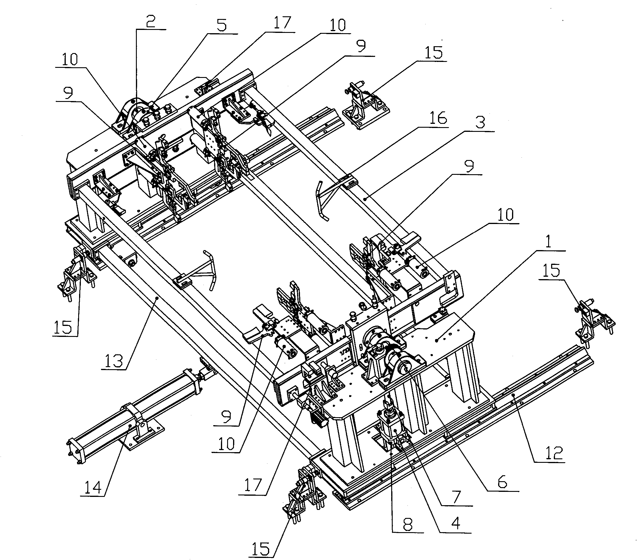
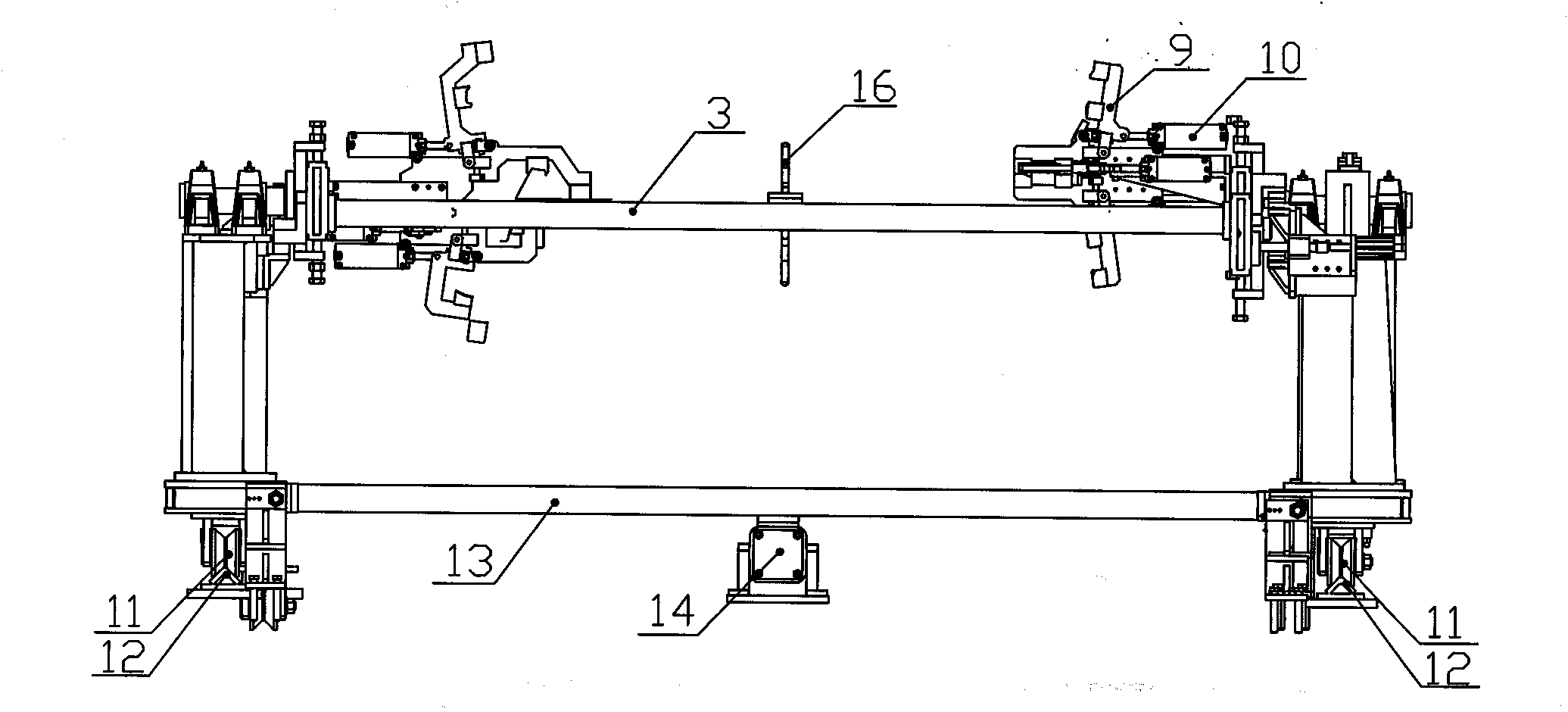
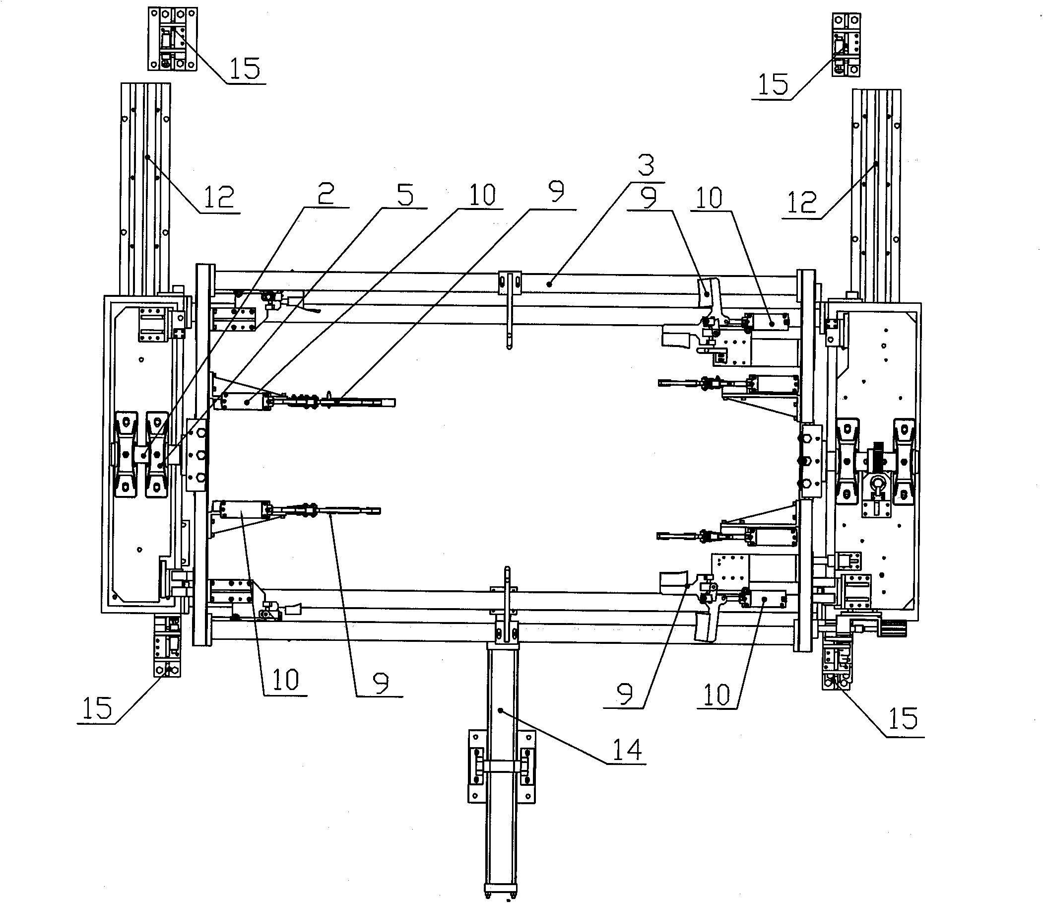
[0025] see figure 1 and figure 2 , an automatic axial overturning mechanism for clamps, including a support seat 1, a rotating shaft 2 is provided at both ends of the supporting seat 1, and a turning frame 3 is connected between the rotating shafts 2, and the rotating shaft 2 can drive the turning frame 3 to rotate through a jacking cylinder 4 .
[0026] The clamp automatic axial overturning mechanism of the present invention is used to replace the manual overturning of the rear floor assembly of the automobile, which has the advantages of high work efficiency, low labor intensity, and no hidden danger in operation, solves the problem of manual handling, and reduces the labor intensity of employees. Reduce sheet metal deformation and bump defects.
[0027] As a preference, the rotating shaft 2 at one end of the support seat 1 is set in the bearing 5, the rotating shaft 2 at the other end is connected to the gear 6, the gear 6 is connected to the rack 7, the rack 7 is arranged on the jacking cylinder 4, and the rack 7 The lower part is connected with the hinge ear of the cylinder, and the hinge ear of the cylinder is connected with the jacking cylinder; the upper part of the rack 7 is connected with the gear 6, and the lower part of the jacking cylinder 4 is connected with the cylinder seat 8, and the cylinder seat 8 is arranged on the support seat 1; 3 is provided with jaws 9, and the jaws 9 are symmetrically arranged on the four corners of the overturn frame 3, wherein two jaws 9 are arranged on one side of the overturn frame 3, and two jaws 9 are arranged below, and one is arranged on the left and right sides. The clamping jaws 9 and the setting of the clamping jaws 9 on the other side are also the same. Each clamping jaw 9 is correspondingly connected to a cylinder 10, and the cylinder 10 can control the closing of the clamping jaws 9 connected thereto.
[0028] Because the rear floor assembly of the car is relatively large and the overall rigidity is not very strong, it is necessary to use multiple jaws to fix it when clamping to prevent the plate from falling during the flipping process.
[0029] In order to enable the workpiece to be accurately positioned when it is put into the reversing frame 3 , a guide rod 16 is respectively provided on the two beams of the reversing frame 3 .
[0030] see image 3 , in order to facilitate the transfer of the turned workpiece to the next process and continue to complete the assembly of the car, there are pulleys 11 under the support base 1, two pulleys 11 on the left and right, and two on the two slide rails 12, and the support base 1 passes through Cross bar 13 is connected, and cross bar 13 is connected bottom cylinder 14. The cylinder at the bottom is connected with the overturning mechanism, and the pulley rolls on the slide rail when advancing to achieve the purpose of operation.
[0031] In order to prevent the pulley from shifting during operation, the bottom cylinder 14 guide rod is deformed, so the slide rail 12 is installed to control the running accuracy. The two ends of the slide rail 12 are provided with buffer seats 15, which are convenient for the mechanism to stop when it is in place.
[0032] A buffer pad 17 is arranged on the support base 1 , and the buffer pad 17 is arranged diagonally between the support base 1 and the turning frame 3 . The main function is to reduce the impact of the impulse force generated by the turning mechanism on the fixture itself.
[0033] Brief description of the mechanism operation of the embodiment of the present invention:
[0034] Lift the workpiece with a pneumatic balance crane, put the workpiece on the flip frame 3 through the guide rod 16, start the cylinder 10, make the jaws 9 clamp the workpiece, start the jacking cylinder 4, and the jacking cylinder 4 pushes the rack 7 to drive the gear 6 rotates, the gear 6 drives the rotating shaft 2 connected to it to rotate, thereby driving the overturning frame 3, the jaws 9 and the workpiece to overturn at the same time; The claw 9 is opened by the cylinder 10, and resets after hoisting the workpiece. The turnover speed of the workpiece can be adjusted by the flow limiting valve to achieve fast and slow speed. The flow limiting valve comes with the cylinder, which is used to control the size of the compressed air passing through the cylinder. Too slow affects the production beat.
[0035] The invention mainly includes a mechanical overturning part and a pneumatic control part. The overturning mechanism adopts a master cylinder CS1T125-300 (bore 125mm, stroke 300mm) SMC standard cylinder as an actuator to overturn 180° axially; the mechanical overturning part uses a rack and pinion mechanism to realize the workpiece Flip function; employees only need to activate the control valve to realize the tooling axial flip 180° during operation, because the air pressure setting requirement of the main pipeline of the body factory is 0.4~0.6Mpa, and the welding air pressure of the workshop shares the air source (welding air pressure pipeline is the controlled parameter of the workshop), so the air source pressure stability of the control device is better; the automatic axial flipping mechanism of the rear floor fixture by 180° is changed from the worker’s flipping to the tooling’s automatic flipping, which reduces the labor intensity of the employees and solves the problem of manual flipping Potential safety hazards have been improved and the quality of the body has been improved.
[0036] The above descriptions are only preferred embodiments of the present invention, and are not intended to limit the present invention. Any modifications, equivalent replacements, improvements, etc. made within the spirit and principles of the present invention shall be included in the protection of the present invention. within range.

PUM

no PUM

Description & Claims & Application Information

We can also present the details of the Description, Claims and Application information to help users get a comprehensive understanding of the technical details of the patent, such as background art, summary of invention, brief description of drawings, description of embodiments, and other original content. On the other hand, users can also determine the specific scope of protection of the technology through the list of claims; as well as understand the changes in the life cycle of the technology with the presentation of the patent timeline. Login to view more.

Similar technology patents

Double-feedback mechanical arm automatic loading and unloading system and method

InactiveCN106826817AGuaranteed precision and efficiencyReduce labor intensity
Owner:河北省自动化研究所有限公司

Semiautomatic revolving roll grinding miller

Owner:大连隆正光饰机制造有限公司

Ray digital imaging detection system for pressure equipment girth welds

InactiveCN101655467ASecurity Data AnalysisReduce labor intensity
Owner:CHINA SPECIAL EQUIP INSPECTION & RES INST

Filtering, cleaning, drying three-in-one device

InactiveCN101455918AReduce labor intensity
Owner:WUXI ZHANGHUA MEDICAL EQUIP

Classification and recommendation of technical efficacy words

  • Reduce labor intensity
  • Improve work efficiency

Method for intelligent automatic identification of transmission circuit parts

Owner:INFORMATION COMM COMPANY STATE GRID SHANDONG ELECTRIC POWER +2

City regional railway signal system and control method thereof

Owner:CHINA RAILWAY SIYUAN SURVEY & DESIGN GRP

Railway bearing intelligent on-line detection method and its device

InactiveCN101290265AReduce labor intensity
Owner:洛阳铭昊测控科技有限公司

Cooperation service platform facing different source data

InactiveCN101174957AImprove management level and qualityImprove work efficiency
Owner:NANJING UNIV OF FINANCE & ECONOMICS

Screw drilling tool, vertical drilling tool testing method and well inclination simulation testing equipment

InactiveCN111594144AReduced height requirementsImprove work efficiency
Owner:DEZHOU UNITED GASOLINEEUM MACHINERY

Method for intelligent automatic identification of transmission circuit parts

Owner:INFORMATION COMM COMPANY STATE GRID SHANDONG ELECTRIC POWER +2

Keyboard spill-proofing mechanism

ActiveUS7030330B2minimize manufacturing costimprove work efficiency
Owner:LITE ON SINGAPORE PTE LTD
Why Eureka
Try Eureka