Hollow forming machine for injecting, drawing and blowing plastic by one-step method

A technology of injection stretch blow molding machine, applied in the direction of hollow objects, other household appliances, household appliances, etc., can solve the problems of product quality not up to standard, increase labor costs, pollution, etc., to improve efficiency, save time, guarantee The effect of product quality

Inactive Publication Date: 2010-11-17
郝恩政
View PDF0 Cites 27 Cited by
  • Summary
  • Abstract
  • Description
  • Claims
  • Application Information

AI Technical Summary

Problems solved by technology

This not only causes the pollution of the preform during the transfer process, but also wastes electricity, increases the footprint of the injection molding machine and the turnover space of the preform, increases labor costs, and increases the burden on

Method used


Image

  • Hollow forming machine for injecting, drawing and blowing plastic by one-step method
  • Hollow forming machine for injecting, drawing and blowing plastic by one-step method
  • Hollow forming machine for injecting, drawing and blowing plastic by one-step method

Examples


Embodiment Construction

[0022] In order to further illustrate the technical means adopted by the present invention and its effects, the following describes in detail in conjunction with preferred embodiments of the present invention and accompanying drawings.

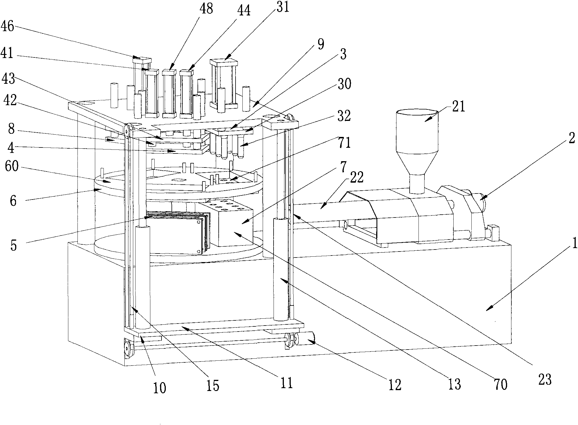
[0023] Such as figure 1 As shown, the present invention provides a one-step injection stretch-blow plastic hollow molding machine, which includes: an installation base 1, an injection device 2 arranged on one side of the installation base 1, a fixing device located on the other side of the installation base 1 Frame 9, injection preform component 3 fixed on the fixed frame 9, stretch blow component 4, blow mold clamping mechanism assembly 5 installed on the installation base 1 and cooperating with the stretch blow component 4, rotary template assembly 6 , be arranged under the injection preform assembly 3 to place the injection station of the preform mold 7, the product release assembly 8, and the quick mold change mechanism 10; the rotary temp...


PUM


Abstract

A hollow forming machine for injecting, drawing and blowing plastic by a one-step method comprises an installation machine base, an injection device, a fixed mount, an injection bottle blank component, a drawing-blowing component, a blow molding die assembly mechanism assembly, a rotary template assembly, an injection station, a product demoulding component and a quick die change mechanism, wherein the injection device is arranged at one side of the installation machine base, and the fixed mount is arranged at the other side of the installation machine seat; the injection bottle blank component is fixed on the fixed mount; the blow molding die assembly mechanism assembly is arranged on the installation machine base and is matched with the drawing-blowing component; the injection station is arranged below the injection bottle blank component and is used for placing a bottle blank die; the rotary template assembly is arranged below the injection bottle blank component; the upper of the rotary template assembly is driven by a power motor to rotate, and the lower thereof is provided with an oil cylinder; a shaped semi-finished bottle blank is injected in the injection bottle blank component; and the oil cylinder drives the rotary template assembly to go up, and then the rotary template assembly is driven by the power motor to rotate so as to drive the semi-finished bottle blank to enter into the position of a drawing-blowing die, thus the rotary template assembly goes down into the drawing-blowing die under the driving of the oil cylinder, and is drawn and blow molded into a finished bottle. The invention achieves circular production, improves production efficiency, saves energy by two thirds as compared with the existing production method, and fills domestic blank.

Description

technical field [0001] The invention relates to the technical field of plastic molding devices, in particular to a one-step injection stretch blow plastic hollow molding machine. Background technique [0002] The existing traditional hollow product molding adopts a "two-step method". The first step is to prepare the preform on the injection molding machine and take it off manually; the second step is to take the injected preform to the blow molding machine for blow molding. This not only causes the pollution of the preforms during the transfer process, but also wastes electricity, increases the footprint of the injection molding machine and the turnover space of the preforms, increases labor costs, and increases the burden on users to purchase machine tools. Based on the many disadvantages of the above-mentioned "two-step method", a "one-step method" method for making hollow products from injection stretch-blow plastics has gradually emerged. To the standard, only rely on i...

Claims


Application Information

Patent Timeline
IPC IPC(8): B29C49/06B29C49/28B29C49/42B29C49/48B29C49/56B29L22/00
Inventor 郝恩政
Owner 郝恩政
Why Eureka
Try Eureka