Diaphragm wall seam waterproof method and diaphragm wall construction method based on same

An underground continuous wall and waterproof board technology, applied in water conservancy projects, infrastructure projects, artificial islands, etc., can solve the problems of hard damage of the formed wall, difficult construction, water leakage and sand production, etc., to ensure construction quality and economic benefits. Significant, simple process effects

Active Publication Date: 2010-11-17
CHINA RAILWAY NO 3 GRP CO LTD
View PDF4 Cites 8 Cited by
  • Summary
  • Abstract
  • Description
  • Claims
  • Application Information

AI Technical Summary

Problems solved by technology

[0006] The present invention solves the problem that the existing underground diaphragm wall construction joint waterproofing method is likely to cause engineering accidents. The construction of the joint pipe method is difficult, and it is easy to cause hard damage to the formed wall. Water leakage and sand often occur during the excavation of the foundation pit in the later stage. cause engineering accidents; the prefabricated "I" joint pile method always has construction joints between the prefabricated piles and the cast-in-place concrete underground diaphragm wall, and the excavation of foundation pits in the later stage is prone to water and sand from the construction joints, resulting in engineering accidents; it provides a Waterproof method for joints of underground diaphragm wall and construction method of underground diaphragm wall based on it

Method used


Image

  • Diaphragm wall seam waterproof method and diaphragm wall construction method based on same
  • Diaphragm wall seam waterproof method and diaphragm wall construction method based on same
  • Diaphragm wall seam waterproof method and diaphragm wall construction method based on same

Examples


Embodiment Construction

[0026] The specific embodiment of the present invention will be further described in conjunction with the accompanying drawings.

[0027] The method of waterproofing the construction joints of the underground diaphragm wall, the steps are as follows:

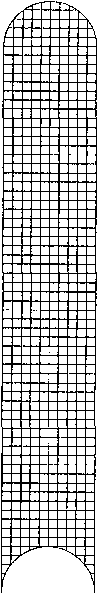
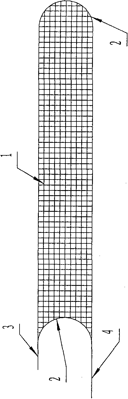
[0028] 1), binding the reinforcement cage 1, the two ends of the reinforcement cage 1 have a concave arc surface at one end, and a convex arc surface at the other end, and the radius of the concave arc surface and the convex arc surface is consistent with the radius of the joint pipe 9, such as figure 1 shown;

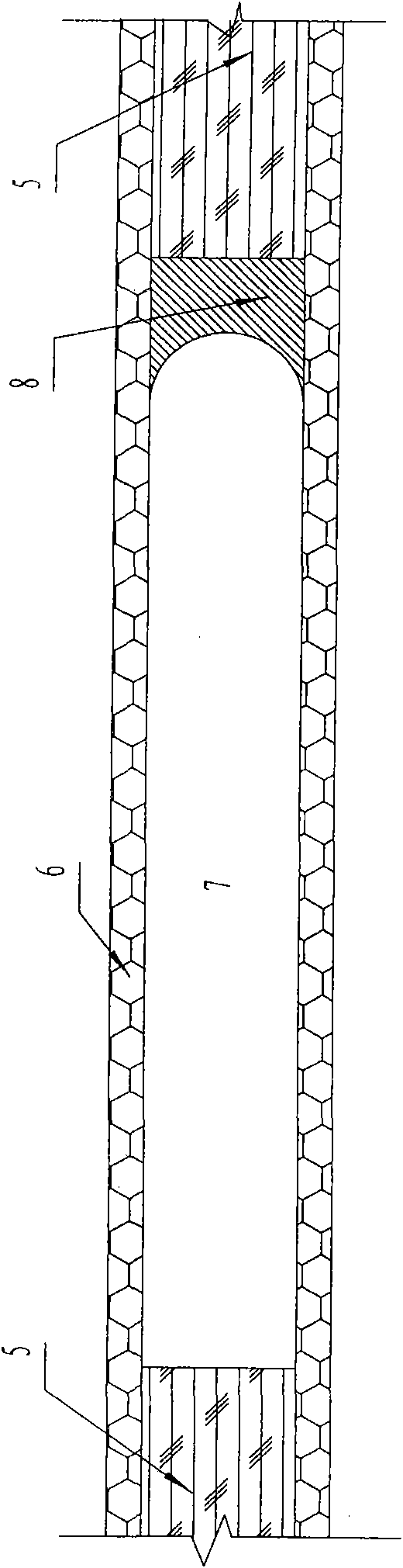
[0029] 2) Weld the same-shaped iron cover 2 on the concave arc surface and the convex arc surface to prevent the direct contact between the joint pipe and the pouring concrete, and the pick-up time of the joint pipe is not limited. The inner side and the outer side of the reinforcement cage 1 at one end of the concave arc surface are welded with waterproof boards, and the length of the outer side waterproof board 4 beyo...


PUM


Abstract

The invention belongs to the technical field of diaphragm wall construction, in particular relates to a diaphragm wall seam waterproof method and a diaphragm wall construction method based on the same, and solves the problem that the conventional seam waterproof method easily causes an engineering accident. The diaphragm wall construction seam waterproof method comprises the following steps of: 1) binding a reinforcement cage, wherein one end face of the reinforcement cage is a concave circular arc surface and the other end face of the reinforcement cage is a convex circular arc surface, and the radius of the concave and convex circular arc surfaces is consistent with that of a joint pipe; and 2) welding iron sheet protective surfaces with the same shape on the concave and convex circular arc surfaces, and welding waterproof plates on inner and outer side surfaces of the reinforcement cage at the end of the concave circular arc surface, wherein the length of the outer side surface waterproof plate beyond the reinforcement cage is greater than that of the inner side surface waterproof plate beyond the reinforcement cage. The diaphragm wall seam waterproof method has the advantages that: the joint waterproof problem is radically solved; the economic effect is obvious; and the pulling of the joint pipe is not limited by time any more and substantially has no disturbance and damage to the diaphragm wall, so the construction quality of the diaphragm wall is guaranteed.

Description

technical field [0001] The invention belongs to the technical field of underground diaphragm wall construction during the excavation of deep and large foundation pits in water-rich areas or during the construction of subway stations, and in particular relates to an underground diaphragm wall joint waterproofing method and an underground diaphragm wall construction method based thereon. Background technique [0002] The existing joint waterproofing technologies in the construction process of underground diaphragm walls mainly include: [0003] ①The seam waterproof technology of the joint pipe method. This is a commonly used waterproof treatment method for underground diaphragm wall joints, that is, after the underground diaphragm wall is grooved and before concrete is poured, joint pipes are placed at both ends of the groove section, a steel cage is placed under the middle of the joint pipe, and then poured into an underground continuous wall. Wall, after the concrete of the...

Claims


Application Information

Patent Timeline
Patent Type & Authority Applications(China)
IPC IPC(8): E02D29/16E02D5/20
Inventor 辛振省张俊兵张宇宁康见星郑保才
Owner CHINA RAILWAY NO 3 GRP CO LTD
Why Eureka
Try Eureka