Two-way thermal expansion valve

A thermal expansion valve, reverse technology, applied in valve details, valve devices, lighting and heating equipment, etc., can solve problems such as different requirements for throttling changes and complex operating environments

Active Publication Date: 2010-11-17
ZHEJIANG SANHUA CLIMATE & APPLIANCE CONTROLS GRP CO LTD
View PDF1 Cites 12 Cited by
  • Summary
  • Abstract
  • Description
  • Claims
  • Application Information

AI Technical Summary

Problems solved by technology

In fact, the operating environment in the refrigeration system is relatively complicated. Considering energy saving, optimal efficiency and service life of the equipment, in different working environments of refrigeration and heating, for specific temperature / pressure parameters, the energy saving of the refrigeration system The flow change requirements are different. In the prior art, the same throttling adjustment part is used for forward and reverse throttling, which cannot achieve this purpose.

Method used

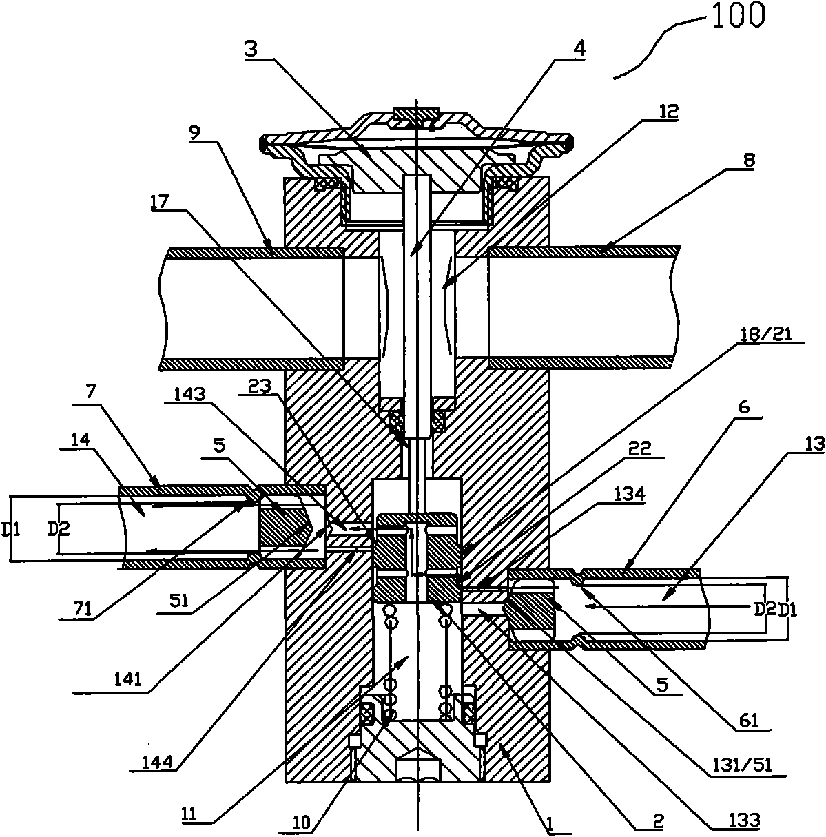
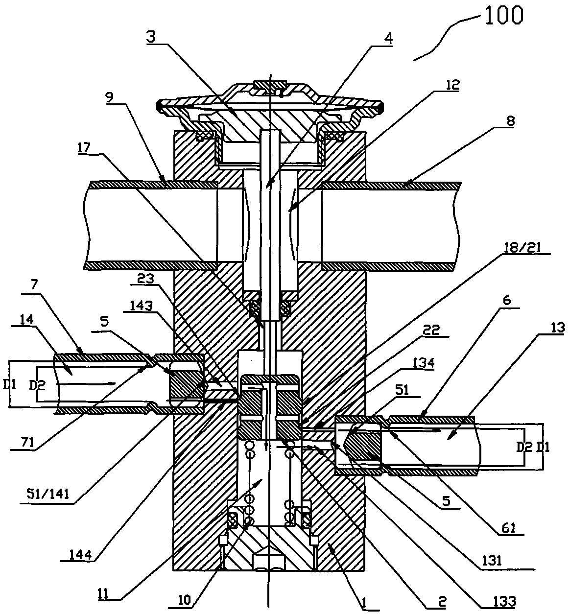
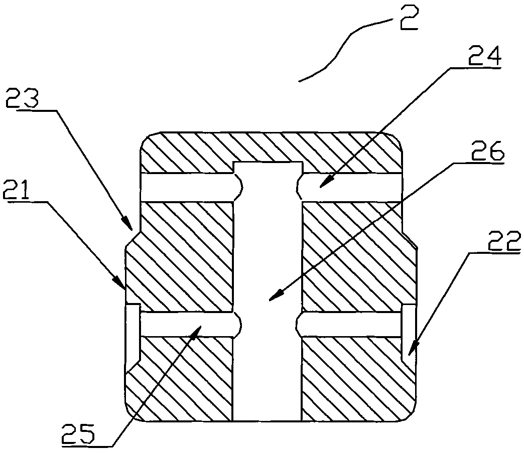

Image

  • Two-way thermal expansion valve
  • Two-way thermal expansion valve
  • Two-way thermal expansion valve

Examples


Embodiment Construction

[0048] The two-way thermal expansion valve of the present invention is suitable for use in refrigeration systems. Since the principles of refrigeration systems are basically the same, a heat pump air-conditioning system is used as an example for illustration below.

[0049] Figure 7 It is a typical refrigeration flow diagram of a refrigeration system in which a bidirectional thermal expansion valve is applied to a heat pump air conditioner. In the refrigeration system, the refrigerant flow path mainly includes: a compressor 101, an electromagnetic reversing valve 102, a bidirectional thermal expansion valve 100, a first heat exchanger 103 (such as an outdoor heat exchanger), and a second heat exchanger 104 ( such as indoor heat exchangers).

[0050] When the air conditioner is in cooling operation, the electromagnetic reversing valve switches 102, and the refrigerant circulation path is: high-pressure gas discharged from the compressor 101 → reversing valve 102 → first heat ...


PUM


Abstract

The invention relates to a two-way thermal expansion valve, which belongs to the technical field of refrigeration control and solves the problems that refrigerants of forward and reverse circulation are throttled by using the same throttle adjusting part and the system design cannot be optimized according to the specificity of a refrigerating or heating stage. The two-way thermal expansion valve comprises a valve body provided with a first chamber and a second chamber, a forward throttle connecting cavity and a reverse throttle connecting cavity communicated with the first cavity, a valve core placed in the first chamber, a temperature sensing component for sensing temperature change in the second chamber, and a transmission bar for connecting the valve core and the temperature sensing component. The two-way thermal expansion valve is characterized in that the valve core is provided with a forward throttle adjusting part and a reverse throttle adjusting part. The refrigerants of forward and reverse circulation are adjusted by the independent throttle adjusting parts so as to fulfill the purposes of improving the energy consumption rate and prolonging the service life of equipment.

Description

technical field [0001] The invention belongs to the technical field of refrigeration control, and is especially suitable for vapor compression heat pump systems (such as air-conditioning systems) and the like. Specifically, it relates to a bidirectional thermal expansion valve structure. Background technique [0002] The expansion valve as a throttling device is widely used in the circuit of the refrigeration system to control the flow of the refrigerant by sensing the temperature / pressure of the refrigerant at a specific location. Such as the Chinese patent that the patent number is 200520013860.5 discloses a kind of such as Figure 6 The structure of the two-way thermal expansion valve shown. This structure includes a valve body 1' with a first chamber 11' and a second chamber 12', a steel ball as a valve core 2' is arranged in the first chamber 11', and at one end of the valve body 1' An air box head 200 as a temperature-sensitive component is fixed, and the air box hea...

Claims


Application Information

Patent Timeline
Patent Type & Authority Applications(China)
IPC IPC(8): F16K31/64F25B41/06
Inventor 王庆勇吕灵秋
Owner ZHEJIANG SANHUA CLIMATE & APPLIANCE CONTROLS GRP CO LTD
Why Eureka
Try Eureka