Fluorescent penetrant detecting method

A fluorescent penetrant and detection method technology, applied in the field of fluorescent penetrant detection, can solve the problems of polluting the surrounding environment, affecting the accuracy of detection, and no obvious improvement in labor intensity, so as to achieve the effect of improving the environment and strengthening the relative sealing effect

Active Publication Date: 2010-11-17
COMAC +1
View PDF1 Cites 26 Cited by
  • Summary
  • Abstract
  • Description
  • Claims
  • Application Information

AI Technical Summary

Problems solved by technology

[0007] But such improvement can only play a limited role, because the main operation work is still carried out manually, especially when the size of the workpiece to be detected is too large to be placed in the tank, the labor intensity of the workers has not been significantly improved; The inspection is not carried out continuously. When the workpiece to be inspected is sent to the next process, it is necessary to open the cover of the tank to take out the workpiece to be inspected, put it on the four-wheel trolley and then send it to the next process by the trolley, so there will still be considerable Part of the fluorescent penetrant and imaging agent enters the surrounding environment, affecting the health of the operators and seriously polluting the surrounding environment; it uses the traditional method of spraying to apply the penetrating agent and the method of fluidized bed to apply the imaging agent, these It does not contribute to improving the utilization rate of the fluorescent penetrant and imaging agent, because the penetrant and imaging agent will still be evenly distributed on the entire workpiece surface, so that most of the penetrating agent and imaging agent are wasted; in addition, Since the penetrant penetrates into the crack completely by capillary action, it is prone to insufficient penetration of the fluorescent penetrant, which makes the detection result not obvious and affects the accuracy of the detection.

Method used


Image

  • Fluorescent penetrant detecting method
  • Fluorescent penetrant detecting method
  • Fluorescent penetrant detecting method

Examples


Embodiment Construction

[0033] Preferred embodiments of the present invention will be described below, by way of example only, with reference to the accompanying drawings. For ease of explanation, the description of the preferred embodiment will be by means of a fluorescent penetrant detection system.

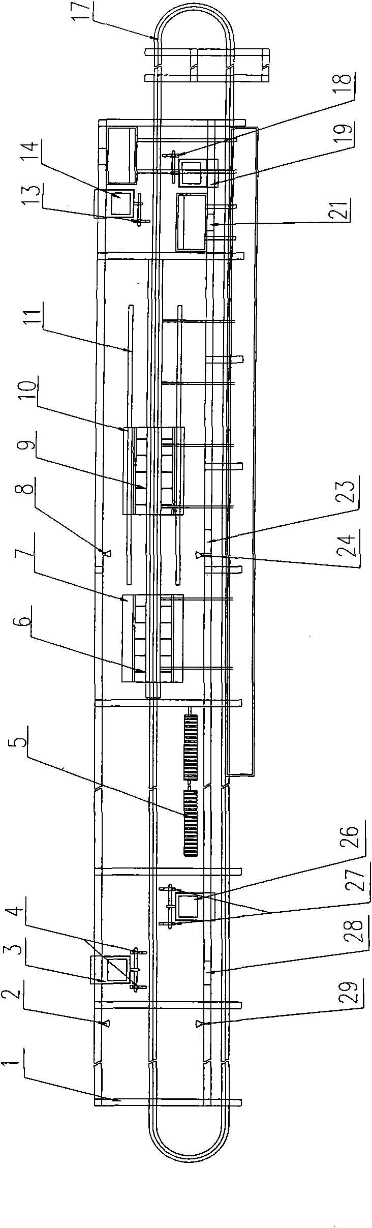
[0034] figure 2It is the overall structural layout diagram of the fluorescent penetrant detection system used to implement the preferred embodiment of the present invention, including: a conveying part, a penetrating agent part, a cleaning part, a drying part, an imaging agent part, a detection part and a control part (Fig. not shown in ).

[0035] Wherein, the penetrating agent application part, the cleaning part, the drying part, the developing agent application part and the detection part are sequentially arranged from right to left, and have independent compartments 1 respectively, wherein the compartments 1 of each part are connected by a large The enclosed compartments are separated by partit...


PUM


Abstract

The invention relates to the part inspection field, and discloses a fluorescent penetrant detecting method. The method comprises the following steps of: providing a relatively closed structure for each unit; loading a workpiece to be detected on a conveying device; conveying the workpiece to be detected to a penetrant application unit to apply a penetrant; conveying the workpiece to be detected to a cleaning unit to finish surface cleaning; conveying the workpiece to be detected to a drying unit to remove surface moisture; conveying the workpiece to be detected to a developer application unit to apply a developer; and finally conveying the workpiece to be detected to a detection unit by the conveying device to perform detection. The method can effectively relieve the labor burden, reduce the production cost and improve the production efficiency, avoids the harm of the penetrant and the developer to the operating personnel, meanwhile avoids cross contamination between the penetrant and the workpiece and between the developer and the workpiece, and eliminates the pollution of the penetrant and the developer to the environment.

Description

technical field [0001] The invention relates to the technical field of component flaw detection, in particular to a fluorescent penetrant detection method. Background technique [0002] In the manufacturing industry, defects such as tiny cracks that exist on the surface of raw materials and parts that are difficult to see with the naked eye often make product quality unable to meet customer requirements. To detect these surface defects, fluorescent penetrant testing technology is widely used in the industry. Its principle is to use a certain method to make the fluorescent penetrant penetrate into the cracks on the surface of the workpiece to be tested, after cleaning and drying to remove the penetrant and moisture on the surface of the workpiece to be tested, and then apply the imaging agent on the surface of the workpiece to be tested, under capillary action , the penetrant in the crack is adsorbed to the surface of the workpiece to be inspected, and then the defect inspec...

Claims


Application Information

Patent Timeline
Patent Type & Authority Applications(China)
IPC IPC(8): G01N21/91G01N21/64
Inventor 陈进春梁富春李进
Owner COMAC
Why Eureka
Try Eureka