Synchronous cold/thermal response ground thermal property tester

A technology of thermal response and cold response, applied in the direction of material thermal development, etc., can solve the problems of difficult to achieve constant heat flow conditions, influence of test results, wrong conclusions, etc., to reduce test costs, solve errors, and improve accuracy.

Inactive Publication Date: 2010-11-17
HARBIN INST OF TECH
View PDF6 Cites 19 Cited by
  • Summary
  • Abstract
  • Description
  • Claims
  • Application Information

AI Technical Summary

Problems solved by technology

[0003] The purpose of the present invention is to solve the problem that only one working condition can be tested at a time when the air source heat pump measuring instrument is used to test the heat exhausting working condition in summer and the heat absorbing working condition in winter. In the process of the second test, the previous test will h

Method used


Image

  • Synchronous cold/thermal response ground thermal property tester
  • Synchronous cold/thermal response ground thermal property tester

Examples


specific Embodiment approach 1

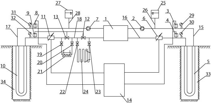
[0007] Specific implementation mode one: combine figure 1 Describe this embodiment. This embodiment includes a water-water heat pump unit 1, a cold response side circulation pump 2, a cold response side return water temperature sensor 3, a cold response side water supply temperature sensor 4, a cold response side U-shaped pipe 5, and a cold response side. Side flow meter 6, thermal response side circulation pump 7, thermal response side return water temperature sensor 8, thermal response side water supply temperature sensor 9, thermal response side U-shaped pipe 10, thermal response side flow meter 11, radiator regulating valve 12, Heater regulating valve 13, data acquisition device 14, cold response side return pipe 15, cold response side water supply pipe 16, heat response side return water pipe 17, heat response side water supply pipe 18, first heater gate valve 19, second heater Gate valve 20, electric heater 21, first radiator gate valve 22, second radiator gate valve 23 ...

specific Embodiment approach 2

[0009] Specific implementation mode two: combination figure 1 Describe this embodiment. The difference between this embodiment and the first embodiment is that it also adds a cold response side expansion tank 25, a cold response side water tank connection 26, a heat response side expansion tank 27, and a heat response side water tank connection 28. The cold response One end of the side water tank connection pipe 26 is connected to the cold response side return pipe 15, the other end of the cold response side water tank connection pipe 26 is connected to the cold response side expansion tank 25, and one end of the heat response side water tank connection pipe 28 is connected to the heat response side return pipe 17, The other end of the heat response side water tank connecting pipe 28 is connected with the heat response side expansion water tank 27 . The expansion tank can accommodate the expanded circulating medium in the instrument system and supplement the circulating medium...

specific Embodiment approach 3

[0010] Specific implementation mode three: combination figure 1Describe this embodiment. The difference between this embodiment and the first embodiment is that it also adds a cold response side return pipe pressure gauge 29, a cold response side water supply pipe pressure gauge 30, a heat response side return pipe pressure gauge 31 and a heat response side. The water supply pipe pressure gauge 32 and the cold response side return pipe pressure gauge 29 are installed on the cold response side return pipe 15, and are located between the cold response side return water temperature sensor 3 and the cold response side U-shaped pipe 5, and the cold response side water supply pipe The pressure gauge 30 is installed on the cold response side water supply pipe 16, and is located between the cold response side water supply temperature sensor 4 and the cold response side U-shaped pipe 5, and the heat response side return pipe pressure gauge 31 is installed on the heat response side retur...


PUM


Abstract

A synchronous cold/thermal response ground thermal property tester relates to a ground thermal property tester. The invention solves the problem that when an air source heat pump type tester is used to test summer heat removal operating condition and winter heat absorption operating condition during the measurement of the ground thermal property, only one operating condition can be tested once and the test result is not accurate. In the tester of the invention, on the cold response side of a water-water heat pump unit, a cold response side water supply pipe, a cold response side flowmeter, a cold response side supply water temperature sensor, a cold response side U tube, a cold response side return water pipe, a cold response side return water temperature sensor and a cold response side circulating pump constitute a loop; and on the thermal response side of the water-water heat pump unit, a thermal response side water supply pipe, a radiator valve, a fin radiator, a heater valve, an electric heater, a thermal response side flowmeter, a thermal response side supply water temperature sensor, a thermal response side U tube, a thermal response side return water pipe, a thermal response side return water temperature sensor and a thermal response side circulating pump constitute the other loop. The synchronous cold/thermal response ground thermal property tester is used in the measurement of the ground thermal property.

Description

technical field [0001] The invention relates to a geotechnical thermophysical property tester. Background technique [0002] Buried pipe ground source heat pump system, as an energy-saving and environment-friendly heat pump system that uses shallow geothermal resources for heating, air conditioning and domestic hot water supply, has been more and more used, but in the actual application process, how to accurately Determining the thermophysical parameters of underground rock and soil is particularly important for system design. At present, there are mainly two types of instruments for measuring thermal physical properties of rock and soil: electric heating tester or air source heat pump tester. Among them, the electric heating tester can only test the heat dissipation conditions in summer, but not the heat absorption work in winter. Therefore, the electric heating tester has limitations; while the air source heat pump tester can test the heat exhausting conditions in summer ...

Claims


Application Information

Patent Timeline
IPC IPC(8): G01N25/20
Inventor 姜益强周群姚杨
Owner HARBIN INST OF TECH
Why Eureka
Try Eureka