

Water-saving urinating discharge blocking device
A plugging device, water-saving technology, applied in water supply devices, flush toilets, urinals, etc., can solve the problems of bad smell, incomplete sealing, easy breeding of bacteria and pests, etc., to achieve obvious water-saving effect, clean and easy to replace effects
- Summary
- Abstract
- Description
- Claims
- Application Information
AI Technical Summary
Problems solved by technology
Method used
Image

Examples
Embodiment 1
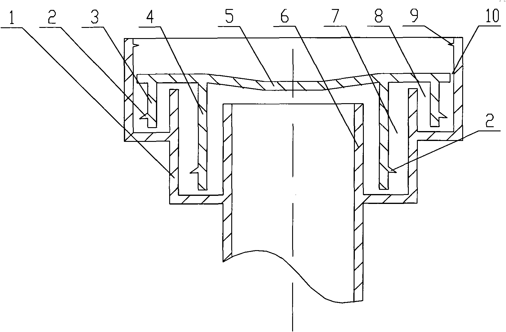
[0026] The structure of the urine discharge blocking device is as follows: figure 1 , the water outlet pipe 6 is set in the center of the water seal box 1, the water outlet pipe 6 is surrounded by a deep ring groove 7, and the shallow ring groove 8 is surrounded by the upper peripheral part of the deep ring groove 7, and the deep ring groove 7 and the shallow ring groove 8 The upper edges of the water retaining ring are kept level with each other or the inner side of the deep ring groove is lower. A cover plate 5 is covered on the water seal box 1, the long water-proof ring 4 provided on the cover plate 5 is inserted in the deep ring groove 7, the short water-proof ring 3 is inserted in the shallow ring groove 8, and the short water-proof ring 2, There is a gap between the lower end of the long water barrier 3 and the bottom surface of the deep ring groove 7 and the shallow ring groove 8, and the top surface of the water retaining ring upper end and the cover plate 5. The upp...
Embodiment 2
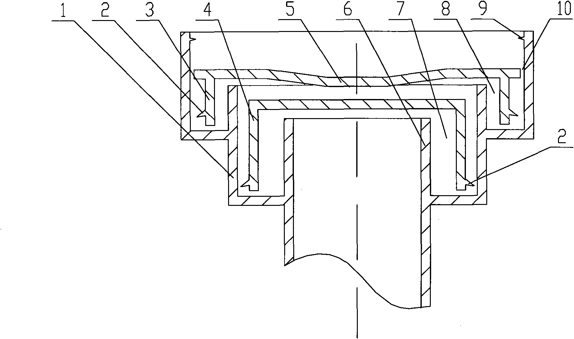
[0029] In the urine discharge blocking device of the present embodiment, the structure of the water seal box 1 is the same as that of the embodiment 1, except that the cover plate 5 is divided into two parts, which are respectively covered on the deep annular groove 7 and the shallow annular groove 8. The outer sides of the two cover plates 5 are all provided with water inlets 10, such as figure 2 shown.
[0030] Wherein, the outer surface of the outer cover plate 5 is set in a concave shape.
Embodiment 3
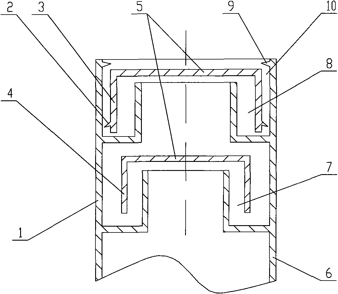
[0032] The structure of the urine discharge blocking device of this embodiment is similar to that of Embodiment 1 and Embodiment 2, except that the deep ring groove 7 and the shallow ring groove 8 are separated and placed in the water seal box 1 one above the other, with the shallow ring groove 8 on the top , below is the deep ring groove 7, and at the same time, the cover plate 5 is also divided into two, covering the deep ring groove 7 and the shallow ring groove 8 respectively, as image 3 shown.
PUM
 Abstract
Description
Claims
Application Information