Rough set-based radar radiation source signal identification method

A signal identification and radiation source technology, applied in the field of signal identification, can solve problems such as large amount of calculation, and achieve the effects of small amount of calculation, avoiding calculation, and fast convergence speed

Inactive Publication Date: 2010-11-24
HARBIN INST OF TECH
View PDF3 Cites 33 Cited by
  • Summary
  • Abstract
  • Description
  • Claims
  • Application Information

AI Technical Summary

Problems solved by technology

[0004] In order to solve the problem of a large amount of calculation due to the need to calculate the least square sum to determine the optimal initial clustering center when using the rough K-means method to identify radar emitt

Method used


Image

  • Rough set-based radar radiation source signal identification method
  • Rough set-based radar radiation source signal identification method

Examples


specific Embodiment approach 1

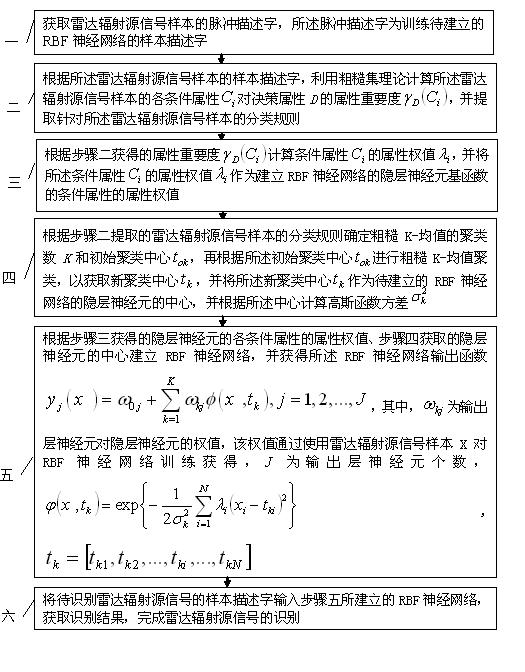
[0014] Specific implementation mode one: according to the instructions attached figure 1 Specifically illustrate this embodiment, a kind of rough set-based radar emitter signal identification method described in this embodiment, it comprises the following steps:

[0015] Step 1: Obtain the pulse description word of the radar radiation source signal sample, and the pulse description word is the sample description word for training the RBF neural network to be established;

[0016] Step 2: According to the sample descriptor of the radar emitter signal sample, use rough set theory to calculate the conditional attributes of the radar emitter signal sample on decision attributes D The attribute importance of , and extract the classification rules for the radar emitter signal samples, where, i =1,2,…, N ;

[0017] Step 3: According to the attribute importance obtained in step 2 Computed conditional properties The attribute weight of , and the condition attribute The a...

specific Embodiment approach 2

[0021] Embodiment 2: This embodiment is a further description of Embodiment 1. In Embodiment 1, in step 2, the radar radiation source is calculated using rough set theory according to the sample description word of the radar radiation source signal sample. Condition properties for signal samples Attribute importance to decision attribute D The specific process is:

[0022] Discretize the sample description words of the radar emitter signal samples according to the equidistant discretization method, and use the rough set theory to process the sample description words, and then obtain the condition attributes The attribute importance of , where | U | is the condition attribute of the radar emitter signal sample the number of POSc ( D ) is the decision attribute D condition attribute set C positive domain.

specific Embodiment approach 3

[0023] Specific implementation mode three: this implementation mode is a further description of specific implementation mode 1 or 2. In specific implementation mode 1 or 2, in step 3, according to the attribute importance obtained in step 2 Computed conditional properties The attribute weight of The specific process is:

[0024] The attribute importance obtained in step 2 normalized to obtain the conditional attribute The attribute weight of ,in, N is the set of conditional attributes C The number of elements in the middle, that is, the condition attribute number.


PUM


Abstract

The invention discloses a rough set-based radar radiation source signal identification method, relates to the technical field of signal identification and solves the problem of large calculated amount because the least square needs to be calculated and an optimal initial clustering center needs to be determined when the radar radiation source signal is identified by the conventional rough K-mean value method. The method comprises the following steps of: firstly, acquiring a pulse description word of a radar radiation source signal sample; secondly, determining a clustering number and the initial clustering center of the rough K-mean value by using rough set theory; thirdly, acquiring the centre of RBF neural network hidden layer neurons by using the rough K-mean value so as to acquire an RBF neural network structure; and finally, inputting the sample description word of the radar radiation source signal to be identified into the RBF neural network, and acquiring the identification result to finish the identification of the radar radiation source signal. The method of the invention is suitable for the identification of the radar radiation source signal.

Description

technical field [0001] The invention relates to the technical field of signal recognition, in particular to a rough set-based radar radiation source signal recognition method. Background technique [0002] Radar emitter signal identification is an important link in the radar system. After the radar emitter signal is sorted and feature extracted, how to accurately analyze its system and provide identification results and decision support for the superior decision-making agency is the key to radar emitter signal identification. main mission. Traditional radar radiation source identification methods mainly include characteristic parameter matching method, artificial intelligence analysis method, intrapulse feature analysis method, data fusion method, etc. Due to the deteriorating electromagnetic environment and the influence of various noises, the signals received by radar reconnaissance receivers are largely polluted and interfered. Traditional recognition methods are powerl...

Claims


Application Information

Patent Timeline
IPC IPC(8): G01S7/41G06N3/08
Inventor 吴芝路尹振东杨柱天匡运生史振国
Owner HARBIN INST OF TECH
Why Eureka
Try Eureka