
Light source device for fluorescence photography

A light source device, color light technology, applied in the direction of fluorescence/phosphorescence, light source, photography, etc., can solve the problem of loss of excitation light source intensity, energy waste and other problems

Active Publication Date: 2010-11-24
YAYATECH
View PDF9 Cites 7 Cited by
  • Summary
  • Abstract
  • Description
  • Claims
  • Application Information

AI Technical Summary

Problems solved by technology

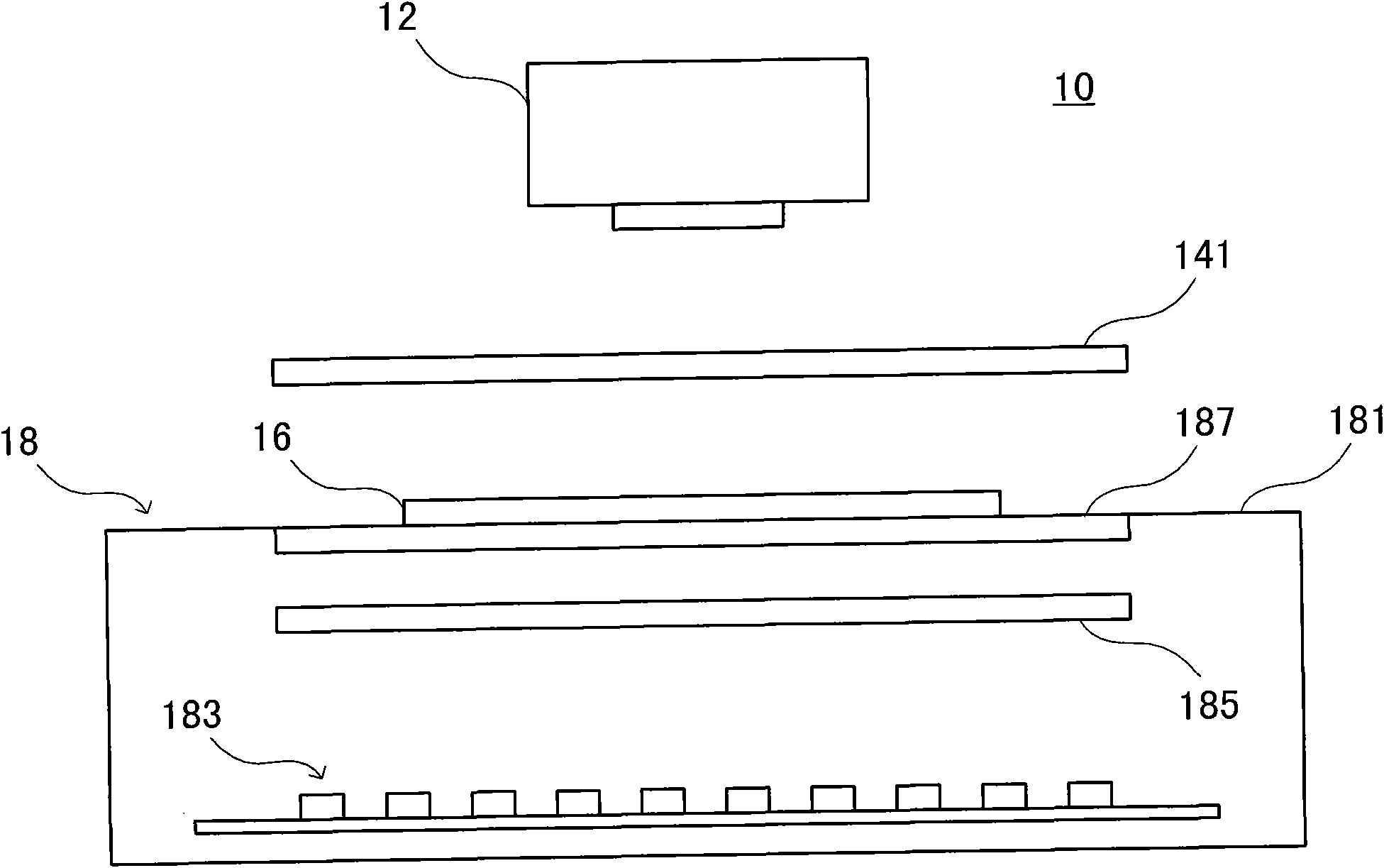
[0009] Although the above-mentioned existing fluorescence photography device can achieve the effects of fluorescence photography and observation, however, due to its structural limitations, one device can only be applied to the application of a single-wavelength excitation light source
And the setting of diffuser 185 in its light source will consume the intensity of excitation light source, cause the waste of energy

Method used


Image

  • Light source device for fluorescence photography
  • Light source device for fluorescence photography
  • Light source device for fluorescence photography

Examples


Embodiment Construction

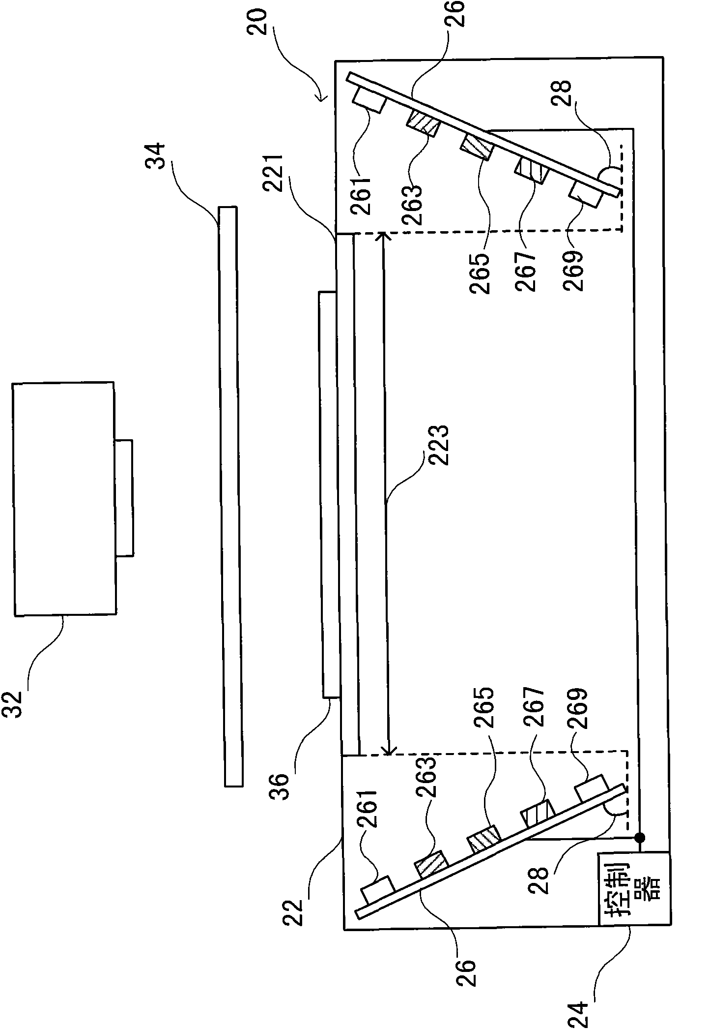
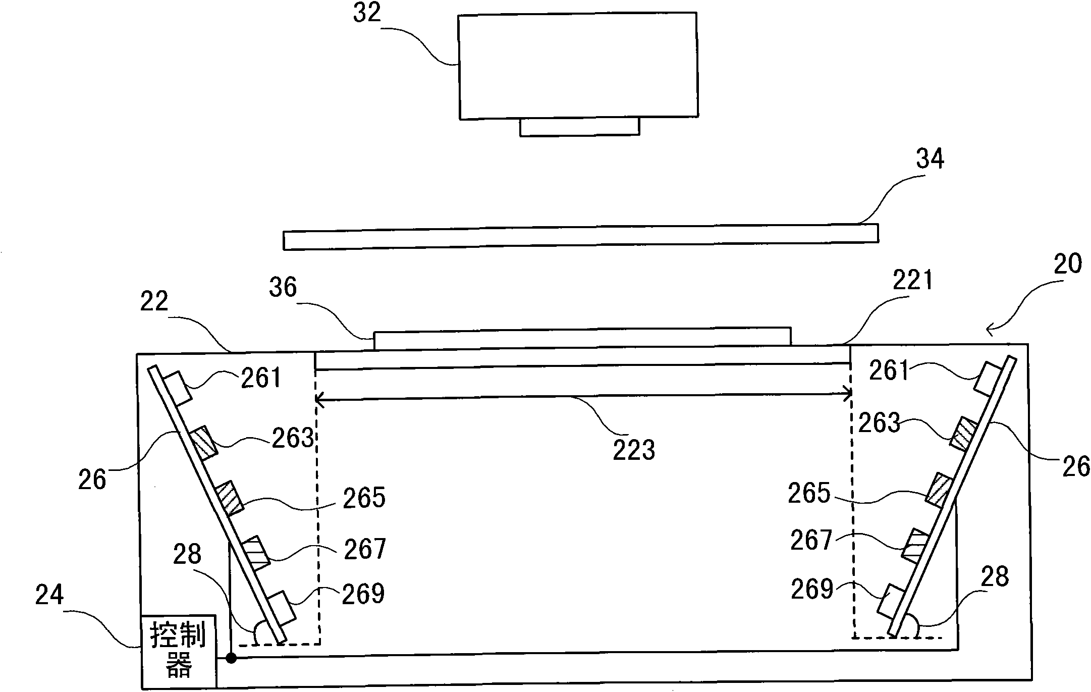
[0043] see figure 2 , which is a schematic cross-sectional view of a preferred embodiment of the present invention. like figure 2 As shown, the light source device 20 for fluorescence photography of the present invention includes a casing 22 , a transparent plate 221 and at least one LED array 26 .

[0044] Wherein, a light-transmitting area 223 is provided above the casing 22 , and a transparent plate 221 is disposed on the light-transmitting area 223 and can be used to carry a biological sample colloid 36 . The light-emitting diode array 26 is disposed outside the coverage of the light-transmitting area 223 inside the housing 22 , and can prevent the bright spots of the light source from interfering with the shooting or observation of fluorescent images by obliquely illuminating them sideways.

[0045] The light source device 20 for fluorescence photography of the present invention is provided with a transparent plate 221 in the light-transmitting area 223, which can all...


PUM


Abstract

The invention discloses a light source device for fluorescence photography, in particular relates to a light source device applied to biological sample colloid fluorescence photography. The light source device mainly comprises a shell, a transparent plate and at least one light-emitting diode array, wherein the transparent plate is arranged in a photic zone of the shell; each light-emitting diode array is arranged in a zone beyond the coverage of the photic zone; and a detection result can be prevented from being interfered by the bright spots of the light source through inclined lateral irradiation. Colored light-emitting diodes can be arranged in each light-emitting diode array; and a controller controls the opening and closing of each colored light-emitting diode. The light source device can be applied to various biological reagents.

Description

technical field [0001] The invention relates to a light source device for fluorescence photography, in particular to a light source device for biological sample colloid fluorescence photography. Background technique [0002] In biotechnology experiments, for all eukaryotic organisms, through protein phosphorylation, the body can change the activity of intracellular proteins, change the activity of enzymes, or transmit signals, regulate cell metabolism, growth, proliferation, and canceration Wait for the physiological process. But generally speaking, the content of phosphorylated protein is extremely low, and it is in a constant dynamic equilibrium in the organism. Without a pre-concentration step, it is often impossible to effectively detect or perform biological tests. [0003] Since Towbin et al. developed protein or nucleic acid (such as deoxyribonucleic acid; DNA) analysis techniques such as Western blot in 1979, Western blot has become a very popular analysis method. ...

Claims


Application Information

Patent Timeline
IPC IPC(8): G03B15/05F21V19/00H05B37/02G01N21/64F21Y101/02
CPCG01N21/6456G01N2201/0627
Inventor 颜硕廷洪伟立
Owner YAYATECH
Learn More