Crystallization of amorphous silicon film as well as manufacture method and device of poly-silicon film
An amorphous silicon thin film, amorphous silicon technology, applied in semiconductor/solid-state device manufacturing, electrical components, circuits, etc., can solve the problems of complex laser crystallization process, difficult maintenance, affecting TFT uniformity, etc., to improve electron migration efficiency, cost savings, and the effect of eliminating lattice defects
- Summary
- Abstract
- Description
- Claims
- Application Information
AI Technical Summary
Problems solved by technology
Method used
Image
Examples
Example Embodiment
[0039] Example 1
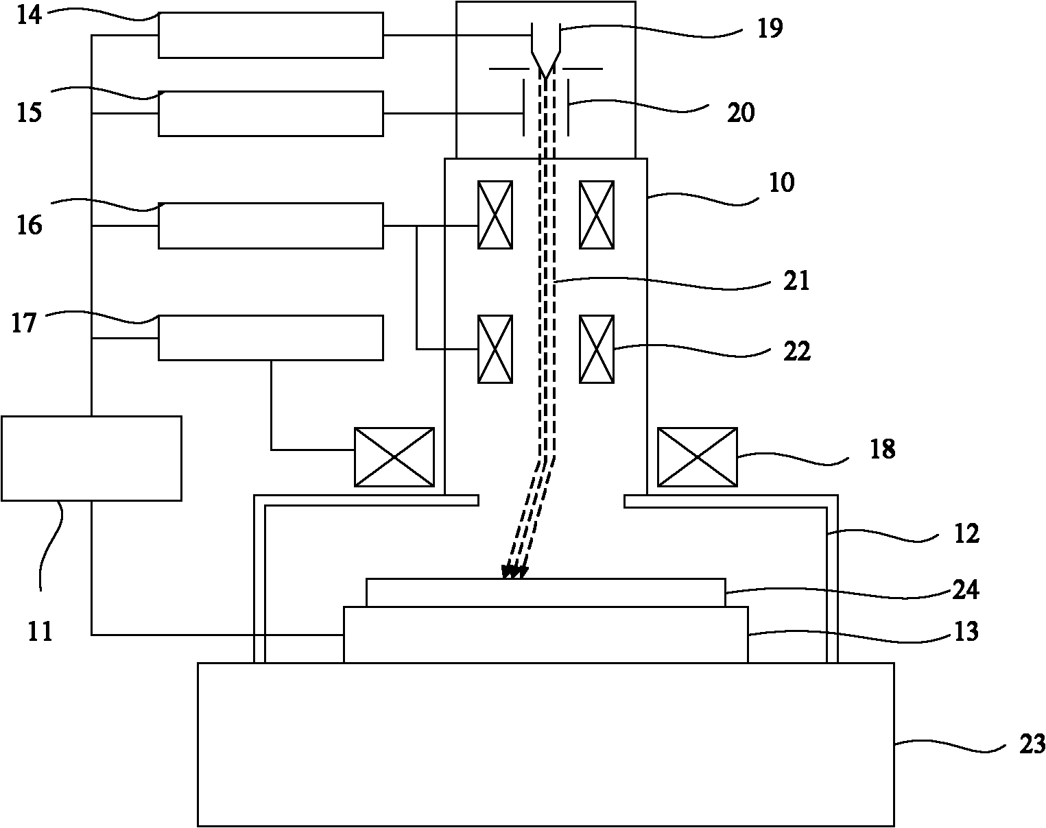
[0040] In this example, the electron beam crystallization device is as image 3 As shown, it mainly includes: an electronic optical system 10 , a computer control system 11 , a vacuum workpiece chamber 12 and a workpiece console 13 placed in the workpiece chamber, and the vacuum workpiece chamber is placed on a shock-proof table 23 . The electron optical system is placed above the workpiece chamber and works by electron beam scanning. Computer control system 11 controls high voltage power supply 14 , grid power supply 15 , electron lens power supply 16 , deflection coil control 17 and workpiece console 13 .
[0041] Among them, the electron optical system is composed of cathode 19, grid 20, electron lens 22, and deflection coil 18. The cathode emits electron beam 21, the grid controls the on-off of the electron beam, the electron lens realizes the focusing of the electron beam, and the deflection coil is fixed on the workpiece. The outer or inner wall of t...
Example Embodiment
[0047] Example 2
[0048] The electron beam crystallization device of this example is as follows: Figure 4 As shown, it mainly includes: an electronic optical system 31 , a computer control system 40 , a vacuum workpiece chamber 29 and a workpiece console 26 placed in the workpiece chamber, and the vacuum workpiece chamber is placed on the shock-proof table 25 . The electron optical system is placed above the vacuum workpiece chamber and works by electron beam scanning. The computer control system controls the high voltage power supply 36, grid power supply 37, electron lens power supply 38, deflection coil control 39 and workpiece console.
[0049] Among them, the electron optical system consists of a cathode 35, a grid 34, an electron lens 33, and a deflection coil 30. The cathode emits an electron beam 32, the grid controls the on-off of the electron beam, the electron lens realizes the focusing of the electron beam, and the deflection coil is fixed on the workpiece. The...
Example Embodiment
[0057] Example 3
[0058] The electron beam crystallization device of this example is as follows: Figure 5 As shown, it mainly includes: an electronic optical system 47, a computer control system 56, a workpiece chamber 44 and a workpiece console 42 placed in the workpiece chamber. The electron optical system is placed above the workpiece chamber and is vacuum sealed with the workpiece chamber. The electron optical system works by electron beam scanning. The computer control system controls the high voltage power supply 52 , the grid power supply 53 , the electron lens power supply 54 , the deflection coil control 55 and the workpiece console 42 .
[0059] Among them, the electron optical system is composed of cathode 51, grid 50, electron lens 49, and deflection coil 45. The cathode emits electron beam 48, the grid controls the on-off of the electron beam, the electron lens realizes the focusing of the electron beam, and the deflection coil is fixed on the workpiece. The o...
PUM
| Property | Measurement | Unit |
|---|---|---|
| Energy density | aaaaa | aaaaa |
| Thickness | aaaaa | aaaaa |
Abstract
Description
Claims
Application Information
 - R&D
- Intellectual Property
- Life Sciences
- Materials
- Tech Scout
- Unparalleled Data Quality
- Higher Quality Content
- 60% Fewer Hallucinations
Browse by: Latest US Patents, China's latest patents, Technical Efficacy Thesaurus, Application Domain, Technology Topic, Popular Technical Reports.
© 2025 PatSnap. All rights reserved.Legal|Privacy policy|Modern Slavery Act Transparency Statement|Sitemap|About US| Contact US: help@patsnap.com


