
Double-frequency broadband wall-mounted antenna

A wall-mounted, broadband technology, applied to antennas, devices that make the antennas work in different bands at the same time, and radiating element structures, etc., can solve the problems of insufficient bandwidth, unacceptable, poor radiation performance indicators, etc. The effect of pattern improvement and antenna bandwidth expansion

Active Publication Date: 2010-11-24
COMBA TELECOM TECH (GUANGZHOU) CO LTD
View PDF3 Cites 15 Cited by
  • Summary
  • Abstract
  • Description
  • Claims
  • Application Information

AI Technical Summary

Benefits of technology

The present in this patented technology allows for smaller size but still improves radioactive efficiency by reducing the total amount of material needed on both sides of an electrically conductive element (E) compared to previous designs that had one side thicker or were made up entirely from metal wire instead of plasma coated glass fiber). This results in better radiating properties without adding too much weight.

Problems solved by technology

This patents discuss different types of wireless communication systems used inside buildings such as Wireless Local Area Network (WLAN) or Bluetooth® devices. These networks use electromagnetic waves with frequencies ranging from 2 GHz upwards towards 5GHz. To improve their efficiency, these signals should be transmitted over long distances without being distorted by interference caused by factors like walls and furniture. Existing methods involve placing an external device at certain points along the path where signal transmission takes place, resulting in increased complexity and cost compared to smaller versions of traditional wireline connections. Therefore there needs better ways to transmit data within specific bands while maintaining good radio wave propagation properties.

Method used


Image

  • Double-frequency broadband wall-mounted antenna
  • Double-frequency broadband wall-mounted antenna
  • Double-frequency broadband wall-mounted antenna

Examples


Embodiment Construction

[0022] Below in conjunction with accompanying drawing and embodiment the present invention will be further described:

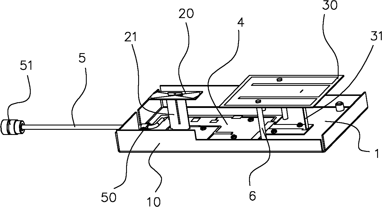
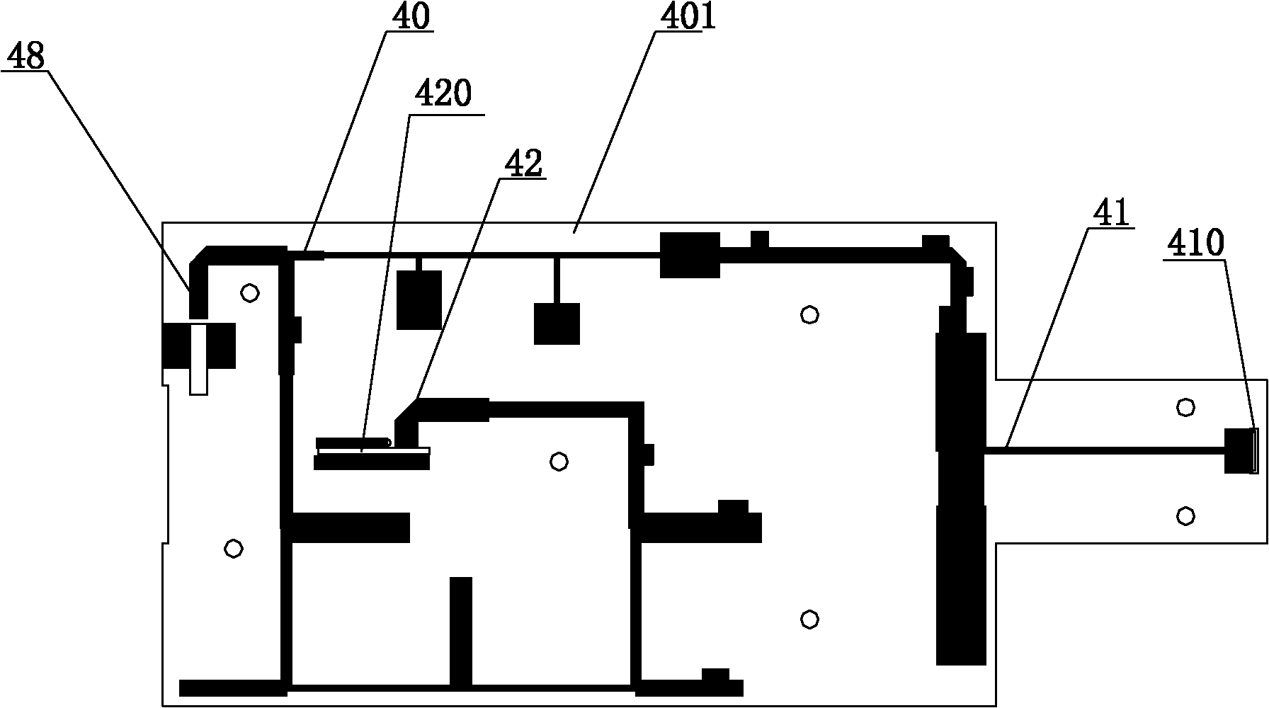
[0023] refer to figure 1 , on a reflective plate 1 made of aluminum with a structure of surrounding flanges 10, a feed network 4 is fixed with screws and nuts, and the upper surface of the feed network 4 is as follows figure 2 As shown, a low-frequency matching network 41, a high-frequency matching network 42, and a duplexer 40 connecting the low-frequency matching network 41 and the high-frequency matching network 42 are printed on a microstrip line. The upper surface of the feeding network 4 corresponds to the low-frequency matching network. 41 and the high-frequency matching network 42, respectively erected low-frequency feeder 31 and high-frequency feeder 21, the low-frequency vibrator 301 is installed above the low-frequency feeder 31, and the high-frequency vibrator is installed above the high-frequency feeder 21 201. In addition to supporting the lo...


PUM

PropertyMeasurementUnit
Angleaaaaaaaaaa
Thicknessaaaaaaaaaa

Abstract

The invention relates to a double-frequency broadband wall-mounted antenna which comprises a reflecting plate, a low-frequency radiating element and a high-frequency radiating element, wherein the reflecting plate is provided with a feed network which feeds the low-frequency radiating element and the high-frequency radiating element; the feed network comprises a medium base plate, a low-frequencymatching network, a high-frequency matching network and diplexer, wherein the low-frequency matching network and high-frequency matching network are printed on the medium base plate by microstrip lines and respectively feed the low-frequency radiating element and the high-frequency radiating element and a diplexer is used for combining/shunting the low-frequency matching network and the high-frequency matching network; and the high-frequency radiating element comprises a half-wave symmetrical high-frequency oscillator, the low-frequency radiating element comprises a low-frequency oscillator, the high-frequency oscillator and the low-frequency oscillator are both realized in the form of the microstrip lines, an oscillator arm of the high-frequency oscillator presents a fan shape, and the low-frequency oscillator integrally presents an E shape. The antenna has the advantages of low profile, broad band, fine radiation performance index and the like.

Description


Claims


Application Information

Patent Timeline
Owner COMBA TELECOM TECH (GUANGZHOU) CO LTD
Learn More