Dual-reflector microwave antenna

A microwave antenna and double-reflecting surface technology, applied to antennas, electrical components, etc., can solve the problems of increased design difficulty, high implementation difficulty, and low antenna radiation efficiency, so as to reduce the difficulty of process design and production, and reduce the shielding area , Increase the effect of radiation range

Active Publication Date: 2010-11-24
HUAWEI TECH CO LTD
View PDF7 Cites 5 Cited by
  • Summary
  • Abstract
  • Description
  • Claims
  • Application Information

AI Technical Summary

Problems solved by technology

The dielectric support 104 has a certain shielding effect on the feed source 103. When the microwave antenna with double reflectors is working, the signal is reflected on the shaped surface of the dielectric support 104. On the arc-shaped shaped surface, the angle of the reflected signal deviates The fold is large and not easy to control, which will cause some signals to easily deviate from the signal receiving range, affect the efficacy and reflection coefficient of the microwave antenna, reduce the antenna radiation efficiency, reduce the antenna gain, and affect the voltage standing wave ratio to a certain extent , for microwave antennas, the maximum value of VSWR is usually 1.3
In the prior art, although a lower VSWR can be obtained by precisely matching the impedance at the port of the feed source 103, the implementation is difficult and costly
[0004] When the signal is radiated to the outside through the feed source 103, in order to prevent part of the signal from being refracted or reflected or directly surrounded by the sub-reflecting surface 105, which will affect the efficacy of the microwave antenna and reduce the radiation efficiency of the antenna, a solution is proposed in the prior art, such as figure 2 As shown, a lateral choke groove 201 is set on one side of the sub-reflecting surface 105, from figure 2 It can be seen that the arrangement direction of the transverse choke grooves 201 is perpendicular to the direction of the central axis of the feed tube 102. However, when the transverse length of the transverse choke grooves 201 is large, the shielding of the feed source 103 will increase, and the antenna radiation efficiency will be low.
[0005] In addition, when the double-reflector microwave antenna receives signals, in order to reduce the reflection of the secondary reflector 105 on the signal reflected by the main reflector 101 and ensure the voltage standing wave ratio, the prior art proposes a solution, such as image 3 As shown, a matching ring 301 is added between the feed source tube 102 and the feed source 103, but the fixing of the matching ring 301 will bring additional material costs, which increases the difficulty of design, and the shape and material of the matching ring 301 have a great impact on the receiver. The signal may also adversely affect the

Method used


Image

  • Dual-reflector microwave antenna
  • Dual-reflector microwave antenna
  • Dual-reflector microwave antenna

Examples


Embodiment Construction

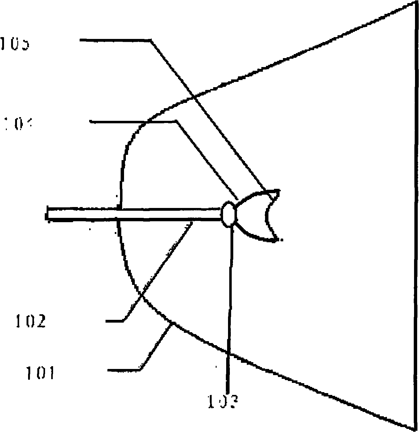
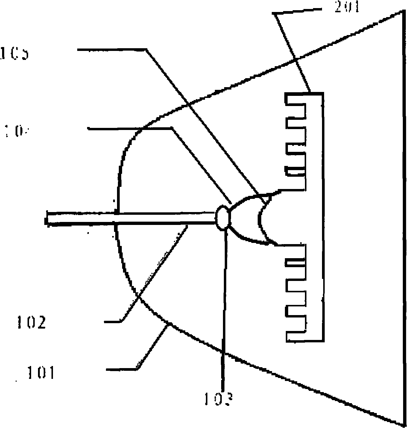
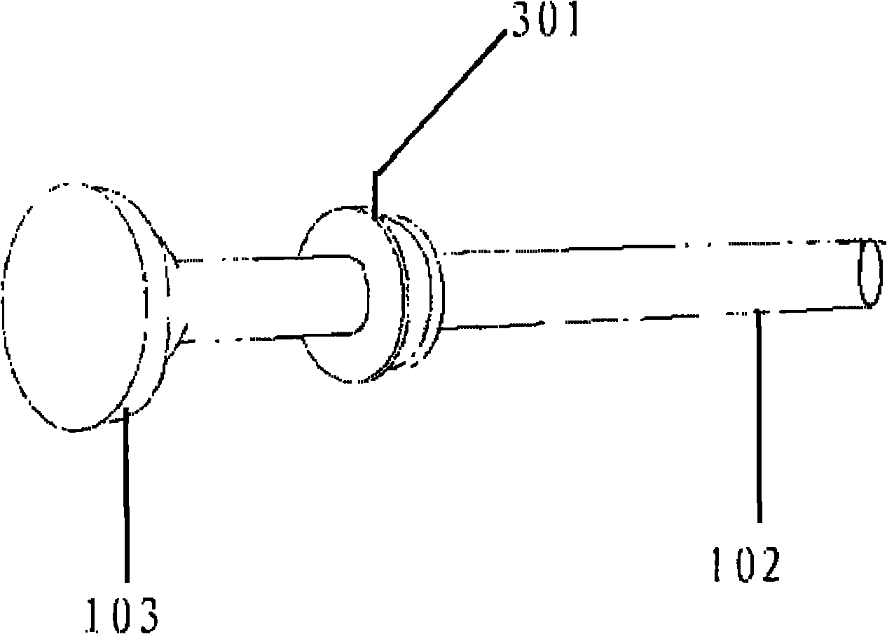
[0021] In order to improve the radiation efficiency of the antenna, obtain high gain, and low voltage standing wave ratio, an embodiment of the present invention provides a dual-reflector microwave antenna. The specific structure is as follows Figure 4 As shown, it includes a main reflecting surface 401 and a secondary reflecting surface 402, and a feed tube 403 connected to the main reflecting surface 401. The feed tube 403 is connected with a feed 404 on one end inside the main reflecting surface 401, and further includes:

[0022] The medium support 405 has one end connected to the feed source 404 and the other end connected to the secondary reflecting surface 402, which is used to multiply the signal sent by the feed source 404 or the signal reflected through the main reflecting surface 401 by using its own stepped shaped curved surface. Times reflection.

[0023] In implementation, the prior art mentions that when the shaped curved surface supported by the medium is arc-shaped...


PUM


Abstract

The invention discloses a dual-reflector microwave antenna which comprises a main reflector, an auxiliary reflector and a feed pipe connected with the main reflector, the feed pipe is connected with a feed at one end on the inner side of the main reflector, and the dual-reflector microwave antenna is characterized by further comprising a medium support, one end of the medium support is connected with the feed, the other end is connected with the auxiliary reflector, and the medium support comprises a ladder-shaped forming curved surface which can carry out multiple reflection on a signal emitted by the feed or the signal reflected by the main reflector. The invention further discloses another two dual-reflector microwave antennas. The adoption of the dual-reflector microwave antenna can upgrade the radiation efficiency of the antenna, and obtain high gain and low voltage standing wave ratio.

Description

Technical field [0001] The present invention relates to the field of microwave antennas, in particular to a dual-reflecting surface microwave antenna. Background technique [0002] With the gradual increase in the application of microwave antennas, the density of microwave sites is getting higher and higher. In order to enhance the efficacy of microwave antennas and better meet microwave communication, it is necessary to obtain microwave antennas that meet the characteristics of high gain and low voltage standing wave ratio. The voltage standing wave ratio refers to the ratio of the maximum value to the minimum value of the antenna load voltage. In the case of short-circuit load and open circuit load, the voltage standing wave ratio is 1 to infinity, and the voltage standing wave ratio is related to the reflection coefficient of the antenna. [0003] The existing microwave antennas usually adopt dual-reflecting surface microwave antennas, and the specific structure is as follows: f...

Claims


Application Information

Patent Timeline
IPC IPC(8): H01Q19/18H01Q19/19H01Q15/14H01Q15/18
Inventor 王天祥肖凌文郭智力姜伟
Owner HUAWEI TECH CO LTD
Why Eureka
Try Eureka