Rotor and motor

一种转子、转子铁心的技术,应用在电动机领域,能够解决没有感应磁通、振动增加、磁通多等问题

Inactive Publication Date: 2010-11-24
ASMO CO LTD
View PDF12 Cites 26 Cited by
  • Summary
  • Abstract
  • Description
  • Claims
  • Application Information

AI Technical Summary

Problems solved by technology

In contrast, in the rotor with the commutated pole structure of the above-mentioned publication, since the salient pole itself does not have the function of inducing magnetic flux, in each case based on the cogging of the salient pole and the stator facing the salient pole, The magnetic flux flowing through the rotor core portion near the back surface of each magnet is unequally separated from the center portion of the magnet in the circumferential direction to both sides in the circumferential direction so that the flux flowing through the salient poles on both sides of the magnet in the circumferential direction The magnetic flux of the salient pole with smaller reluctance is more
That is to say, since the directionality of the magnetic flux of the salient pole portion and the magnetic flux change based on the positional relationship between the salient pole and the cog slot, the rotor is magnetically unbalanced, resulting in a decrease in torque and an increase in vibration, etc., and the rotational performance of the motor occurrence of deterioration

Method used


Image

  • Rotor and motor
  • Rotor and motor
  • Rotor and motor

Examples


Embodiment Construction

[0061] Next, a first embodiment embodying the present invention will be described with reference to the drawings.

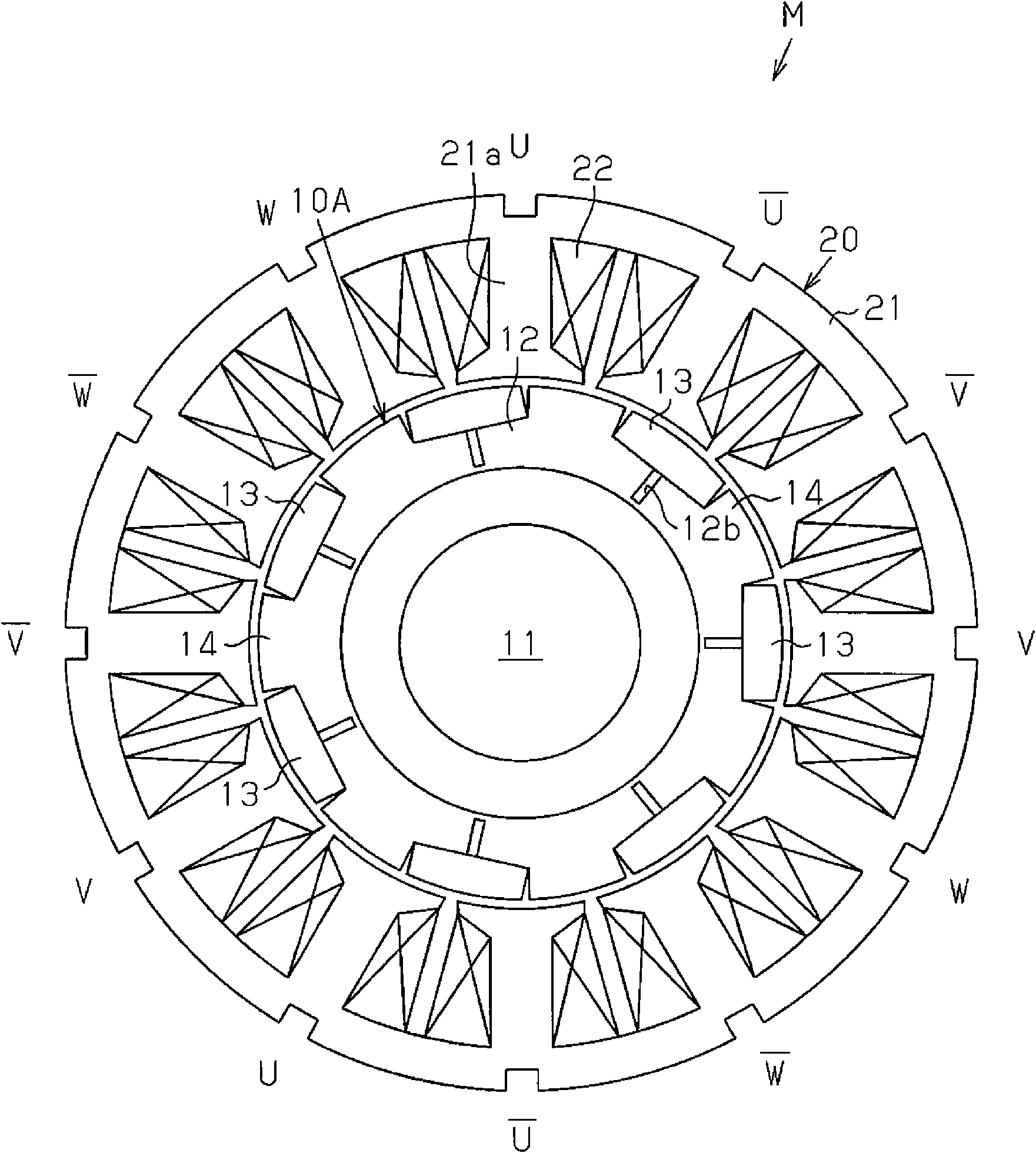
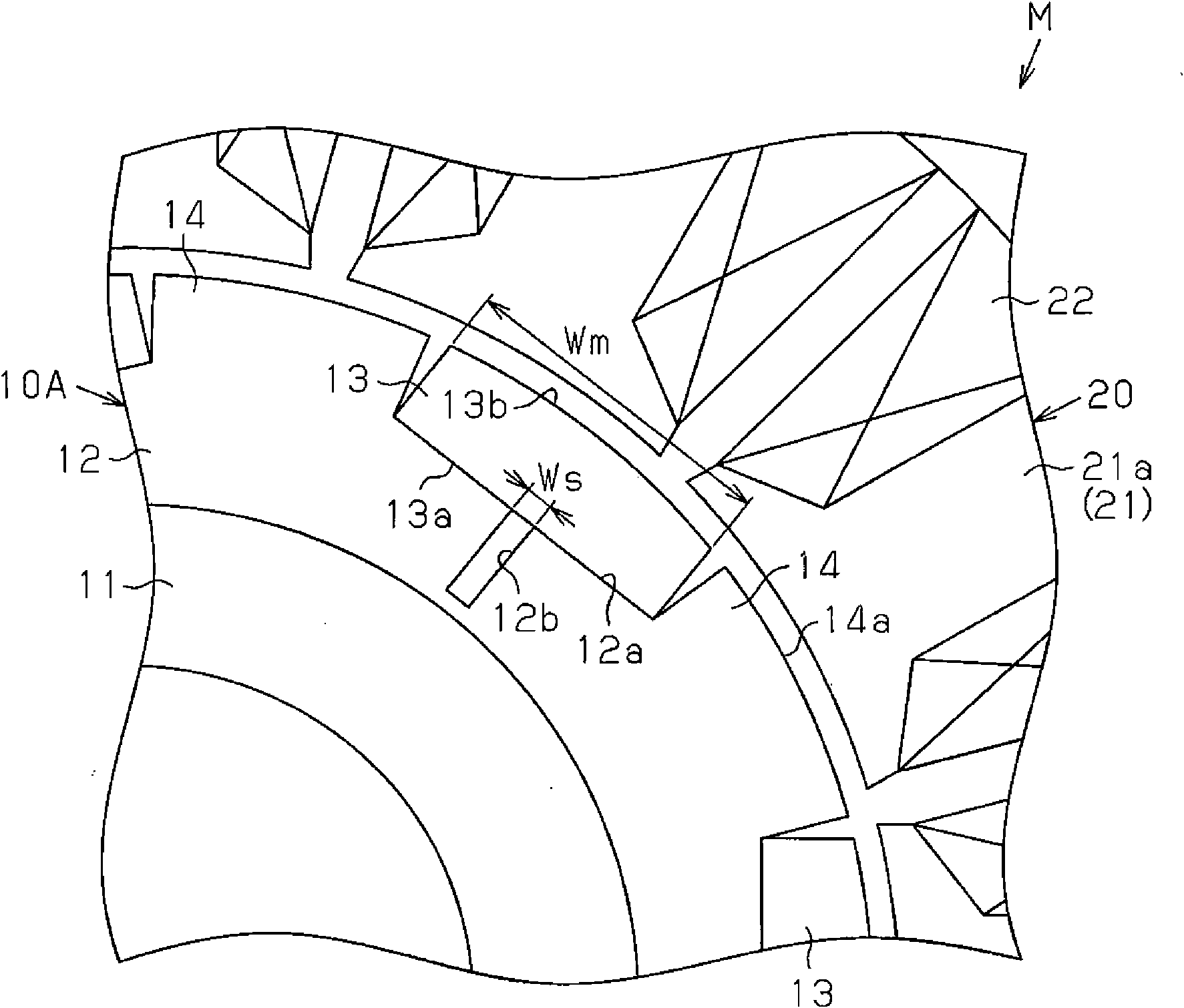
[0062] figure 1 as well as figure 2 A brushless motor M of an inner rotor type is shown. The rotor 10A used in the motor M of the present embodiment is provided with a substantially annular rotor core 12, seven magnets 13, and seven salient poles 14, wherein the rotor core 12 is formed of a magnetic metal material and fixed On the outer peripheral surface of the rotating shaft 11, the seven magnets 13 are fixed on the outer peripheral surface of the rotor core 12 in the form of arranging along the circumferential direction, and the seven salient poles 14 are arranged on the outer circumference of the rotor core 12. surface, and between magnets 13 adjacent in the circumferential direction. Each magnet 13 functions as an N pole. Each salient pole 14 is integrally formed with the rotor core 12 and functions as an S pole. The rotor 10A is a commutated pole type...


PUM

PropertyMeasurementUnit
angleaaaaaaaaaa

Abstract

A motor is disclosed that includes a rotor having a consequent-pole structure. The rotor core of the rotor includes a magnetic flux dividing portion at each position that faces one of the magnets. Each magnetic flux dividing portion forcibly divides magnetic flux in the vicinity of the backside of the corresponding magnet to both sides in the circumferential direction.

Description

technical field [0001] The present invention relates to a rotor with commutated pole structure, and a motor equipped with the rotor. Background technique [0002] As a rotor used in an electric motor, for example, a rotor having a commutated pole structure disclosed in JP-A-9-327139 is known. The rotor of the above-mentioned publication includes a rotor core, a plurality of magnets, and a plurality of salient poles, wherein the magnets are arranged along the circumferential direction of the rotor core, and the plurality of salient poles are arranged between magnets adjacent in the circumferential direction. The form is integrated with the rotor core. Each of the magnets functions as one of an N pole and an S pole, and each salient pole functions as a magnetic pole different from the magnetic pole of the magnet. [0003] However, in a general rotor in which all magnetic poles are composed of magnets, since the magnetic flux flowing through the rotor core portion near the ba...

Claims


Application Information

Patent Timeline
Patent Type & Authority Applications(China)
IPC IPC(8): H02K1/27H02K1/28
CPCH02K29/03H02K1/2746
Inventor 山田洋次横山诚也加藤茂昌竹本佳朗立石畅子
Owner ASMO CO LTD
Why Eureka
Try Eureka