Armature in rotary electric device and its manufacturing method

A technology of rotating electric machines and manufacturing methods, applied in the manufacture of motor generators, electrical components, electromechanical devices, etc., can solve problems such as magnetic imbalance, achieve the effects of improving magnetic balance, reliable fixing, and reducing the mixing of windings

Active Publication Date: 2011-08-24
MITSUBA CORP
View PDF1 Cites 0 Cited by
  • Summary
  • Abstract
  • Description
  • Claims
  • Application Information

AI Technical Summary

Problems solved by technology

However, it is well known that in this type of motor, when the ends of the coil are wound and connected so that the commutator segments and the winding position of the coil are overlapped and wound in a state substantially facing each other in the axial direction, magnetic distortion will occur. Unbalanced, resulting in shimmy rotation due to torque fluctuations, etc.

Method used


Image

  • Armature in rotary electric device and its manufacturing method
  • Armature in rotary electric device and its manufacturing method
  • Armature in rotary electric device and its manufacturing method

Examples


Embodiment Construction

[0031] Next, a first embodiment of the present invention will be described with reference to the drawings.

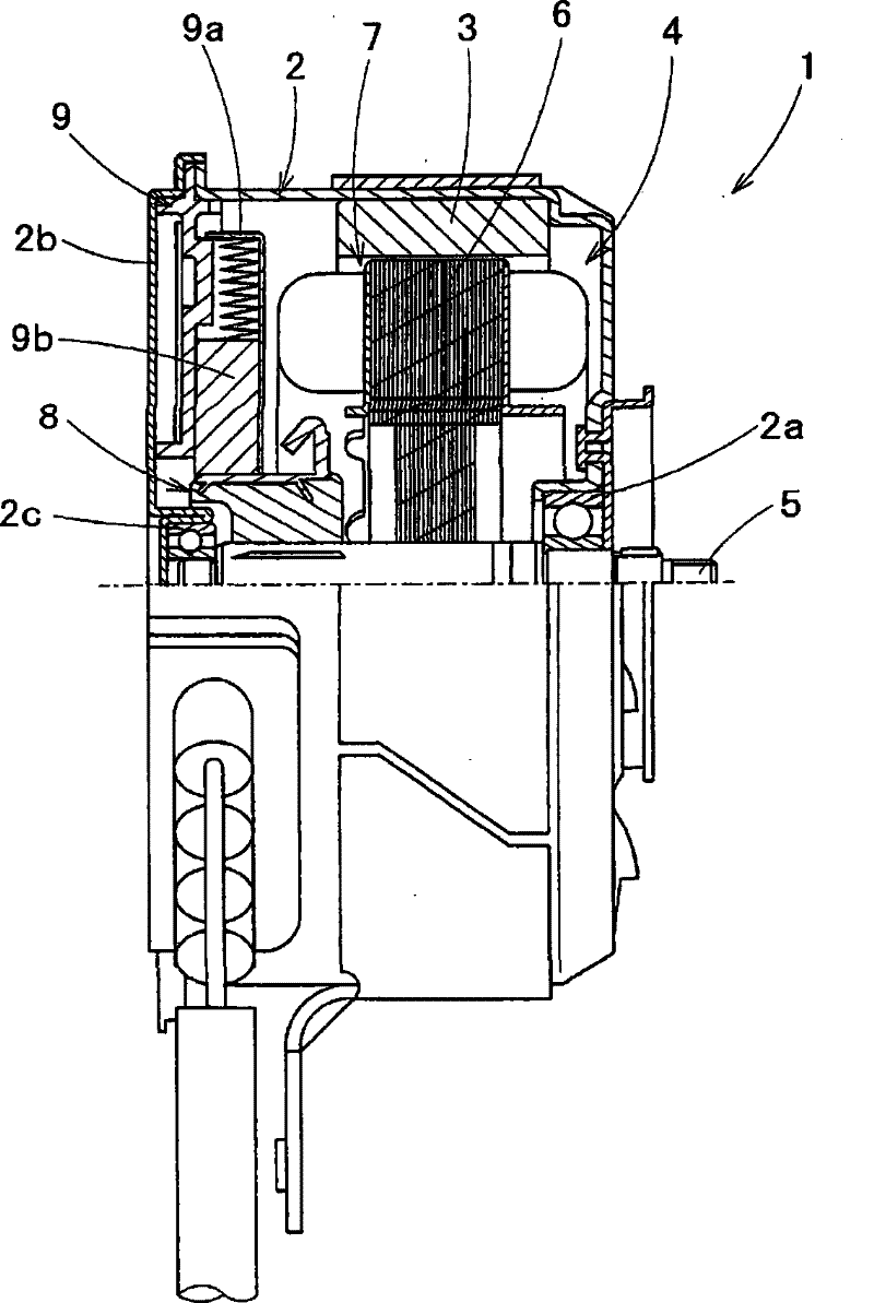
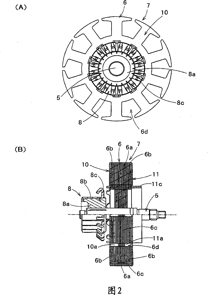
[0032] In the figure, 1 is an electric motor (rotating electric machine) as a driving source of an electrical component mounted on a vehicle, and on the inner peripheral surface of a bottomed cylindrical yoke (motor housing) 2 constituting the electric motor 1 , along A permanent magnet 3 for forming two pairs of N and S poles is fixed along the circumferential direction, thereby forming a four-pole motor 1 with the same magnetic poles facing along the radial direction. 4 is an armature, and a plurality of ring-shaped plates The armature core 7 formed by stacking the core material 6 is integrally embedded on the armature shaft 5 constituting the armature 4, and furthermore, the commutator 8 is externally embedded and fixed at the position of the front end of the armature core 7. . Further, the armature shaft 5 is pivotally supported at its proximal end by the yoke 2 vi...


PUM


Abstract

In a rotary motor whose commutator piece number is set twice of the slot number, a favorable magnetic balance mode is used to wind the windings wound onto the armature. A first winding connected to arbitrary commutator piece (8b) and another commutator piece adjacent to the commutator piece in the periphery direction, is wound between slots (6d) opposite to a permanent magnet of a magnetic pole, in a positive direction winding mode; meanwhile a second winding connected to a commutator piece adjacent to the arbitrary commutator piece in the other direction of the periphery direction, is wound between slots (6d) opposite to the other magnetic pole, in negative direction winding mode, and then going back between the initial slots (6d), thereby forming two windings.

Description

technical field [0001] The present invention relates to the technical field of an armature in a rotating electric machine mounted on a vehicle or the like and a manufacturing method thereof. Background technique [0002] Generally, as such a rotating electrical machine, a motor having a structure equipped with: a yoke provided with magnetic poles composed of pairs of permanent magnets on an inner peripheral surface; an armature, The armature is formed with a plurality of slots long in the axial direction and formed along the circumferential direction on the outer periphery of the core, and the armature is formed by winding a plurality of slots between the slots with a predetermined gap. A coil formed by conduction between the winding wire and adjacent commutator pieces; and a yoke provided with magnetic poles. In such a motor, when high torque and downsizing are required, the number of pairs of permanent magnets is increased to make the motor multi-polarized, or the number ...

Claims


Application Information

Patent Timeline
Patent Type & Authority Patents(China)
IPC IPC(8): H02K23/26H02K15/09H02K3/28H02K23/04H02K13/04
CPCH02K23/32H02K23/30Y10T29/49009
Inventor 田口昌基
Owner MITSUBA CORP
Why Eureka
Try Eureka