Method and device for realizing all-fiber protection

An all-optical fiber and optical link terminal technology, applied in the direction of selection devices, multiplexing system selection devices, electrical components, etc., can solve problems such as unfavorable network condition monitoring, unfavorable protection system configuration, and link failure. Achieve the effect of improving configurability and manageability, and improving system practicability

Active Publication Date: 2010-11-24
NANJING ZHONGXING SOFTWARE
View PDF3 Cites 10 Cited by
  • Summary
  • Abstract
  • Description
  • Claims
  • Application Information

AI Technical Summary

Problems solved by technology

[0005] 1. There is no specific definition and difference between the request level of command switching and the alarm level generated by optical link failure, which is not conducive to the monitoring of network conditions, nor to the configuration of the entire protection system according to specific needs
[0006] 2. In networking, in order to make channel switching correct, it is necessary to manually ensure that the active PON port on the Optical Line Terminal (OLT) corresponds to the active PON port on the Optical Network Unit (ONU). The standby PON port of the ONU corresponds to the standby PON port of the ONU, which is difficult to achieve in practical applications
[0007] 3. There is a lack of heartbeat packets between the OLT and the ONU that can keep the link consistent. In the application, the link channel is likely to be inconsistent, resulting in the problem of link failure.

Method used


Image

  • Method and device for realizing all-fiber protection
  • Method and device for realizing all-fiber protection
  • Method and device for realizing all-fiber protection

Examples


Embodiment Construction

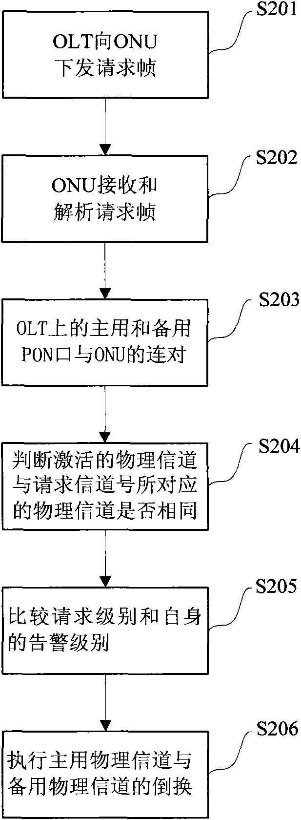
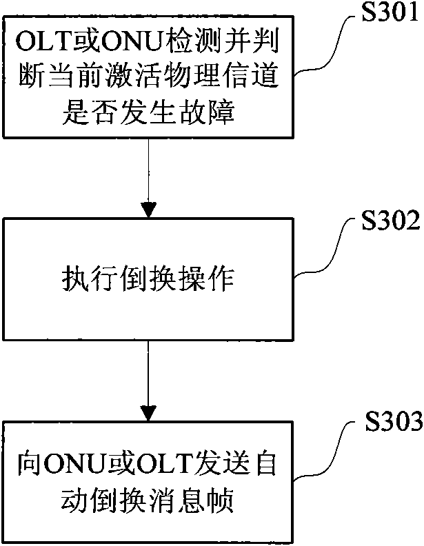
[0028] The preferred embodiments of the present invention will be described in detail below in conjunction with the accompanying drawings. It should be understood that the preferred embodiments described below are only used to illustrate and explain the present invention, and are not intended to limit the present invention.

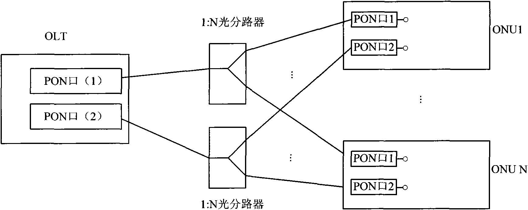
[0029] figure 1 shows a schematic diagram of an all-fiber protection network according to an embodiment of the present invention, as shown in figure 1 As shown, each ONU is connected to two independent 1:N optical splitters through two PON ports, and the other end of one 1:N optical splitter is connected to a PON port of the OLT, and the other 1:N optical splitter The other end of the N optical splitter is connected to another PON port of the OLT. Among them, the OLT is the leading device of the EPON system. Users can configure various request states through the man-machine interface provided on the OLT; the ONU is a passive device that performs switchin...


PUM


Abstract

The invention discloses a method and a device for realizing all-fiber protection, and relates to the technical field of optical fiber access. The method comprises the following steps that: an optical link terminal OLT sends a request frame containing a request channel number and a request level to an optical network unit ONU through a primary physical channel or a spare physical channel; the ONU judges whether the physical channel activated currently is identical with a physical channel to be rearranged corresponding to the request channel number according to the request channel number analyzed by the request frame; if a judging result is that the physical channel activated currently is identical with the physical channel to be rearranged corresponding to the request channel number, the ONU maintains the physical channel activated currently; and if the judging result is that the physical channel activated currently is different from the physical channel to be rearranged corresponding to the request channel number, the ONU executes the operation of reversing the primary physical channel and the spare physical channel according to the request channel number, the request level and an alarm level, which are analyzed by the request frame. The method and the device improve the practicability, configurability and manageability of a system greatly, so that the integral system is more flexible and meets various application requirements.

Description

technical field [0001] The invention relates to the technical field of optical fiber access, in particular to a method and device for all optical fiber protection of an Ethernet passive optical network EPON system. Background technique [0002] Ethernet Passive Optical Network (EPON) is a new type of optical fiber access network technology. It adopts a point-to-multipoint structure and passive optical fiber transmission to provide various services on the Ethernet. It adopts passive optical network (Passive Optical Network, PON) technology in the physical layer, uses the Ethernet protocol in the link layer, and realizes the access of the Ethernet by using the topological structure of the PON. Therefore, it integrates PON technology and Ethernet technology, and has the advantages of low cost, large bandwidth, strong scalability, flexible and fast service reorganization, and compatibility with existing Ethernet and convenient management. [0003] In recent years, the user scal...

Claims


Application Information

Patent Timeline
Patent Type & Authority Applications(China)
IPC IPC(8): H04Q11/00H04B10/12H04B10/038
Inventor 马兴睿李二洁武云飞郭洪涛
Owner NANJING ZHONGXING SOFTWARE
Why Eureka
Try Eureka