Injector

A technology of injection device and screw, which is applied in the field of injection device, can solve problems such as taking a long time, increasing heat release, and resin ablation

Active Publication Date: 2010-11-24
SUMITOMO HEAVY IND LTD +1
View PDF6 Cites 2 Cited by
  • Summary
  • Abstract
  • Description
  • Claims
  • Application Information

AI Technical Summary

Problems solved by technology

[0013] However, in the conventional injection device, such as figure 2 As shown, the resin supplied through the resin supply port 25 is flocculated in the groove 24 while advancing in the direction of the arrow, resulting in the formation of a solid bed b composed of a plurality of resin particles 19 in the molten pool r
[0014] In this solid bed b, the particles 19 existing on the outside easily transfer heat, and on the contrary, the particles 19 existing on the inside are difficult to transfer heat, so it takes a long time for all the particles 19 to melt.
Therefore, the heat of the heaters h1 to h3 cannot be efficiently transferred to all the resins.
[0015] Also, since a plurality of particles 19 are overlapped in the depth direction of the groove 24 to form a solid bed b, the heat capacity becomes large, and even if shear heat occurs in the resin, as image 3 As shown, the expansion distance L1 until the resin is completely melted becomes longer
[0016] As a result, the screw 14 needs to

Method used


Image

  • Injector
  • Injector
  • Injector

Examples


Embodiment Construction

[0041] Hereinafter, embodiments of the present invention will be described in detail with reference to the drawings. At this time, an injection molding machine as a molding machine will be described.

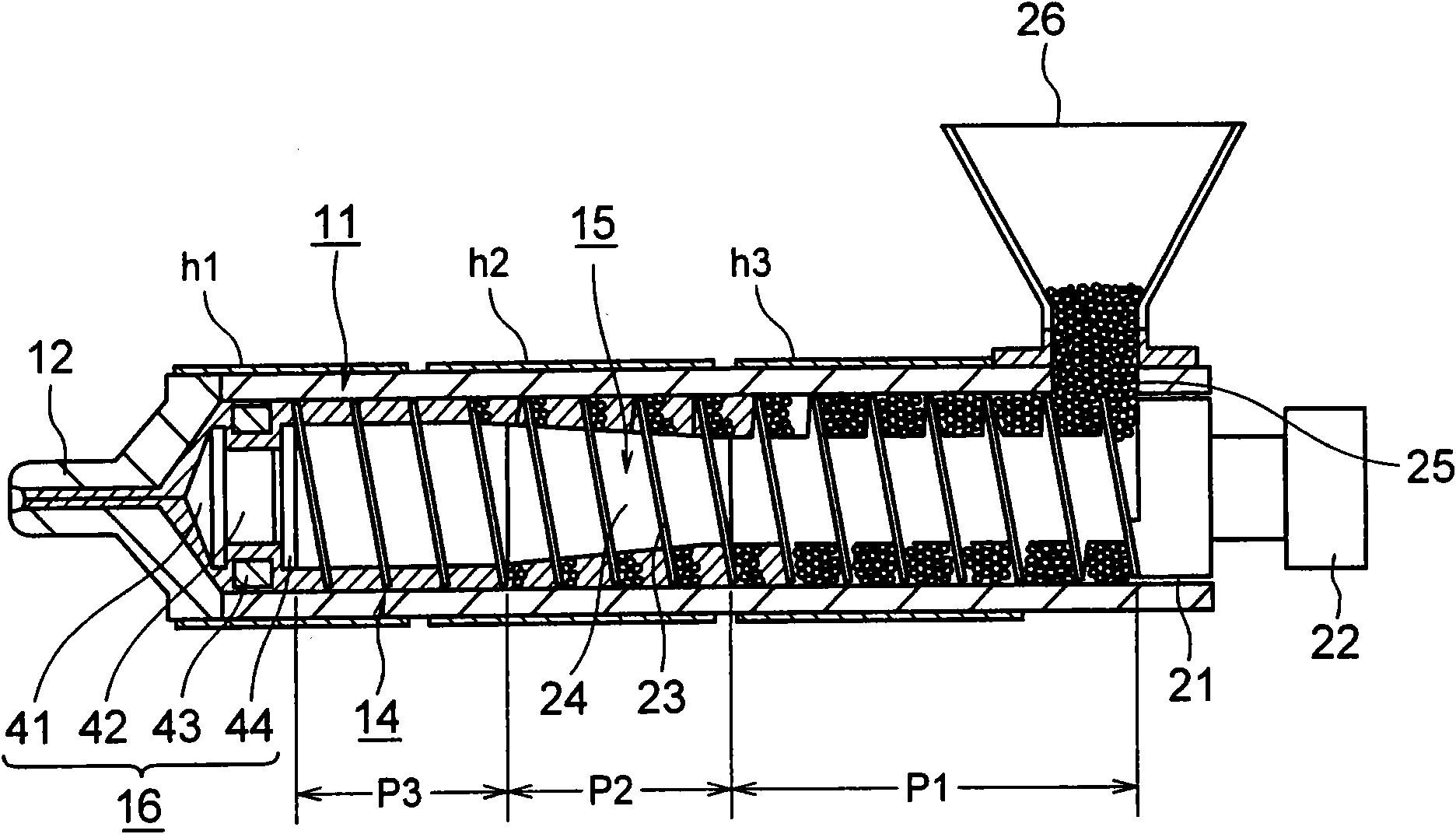
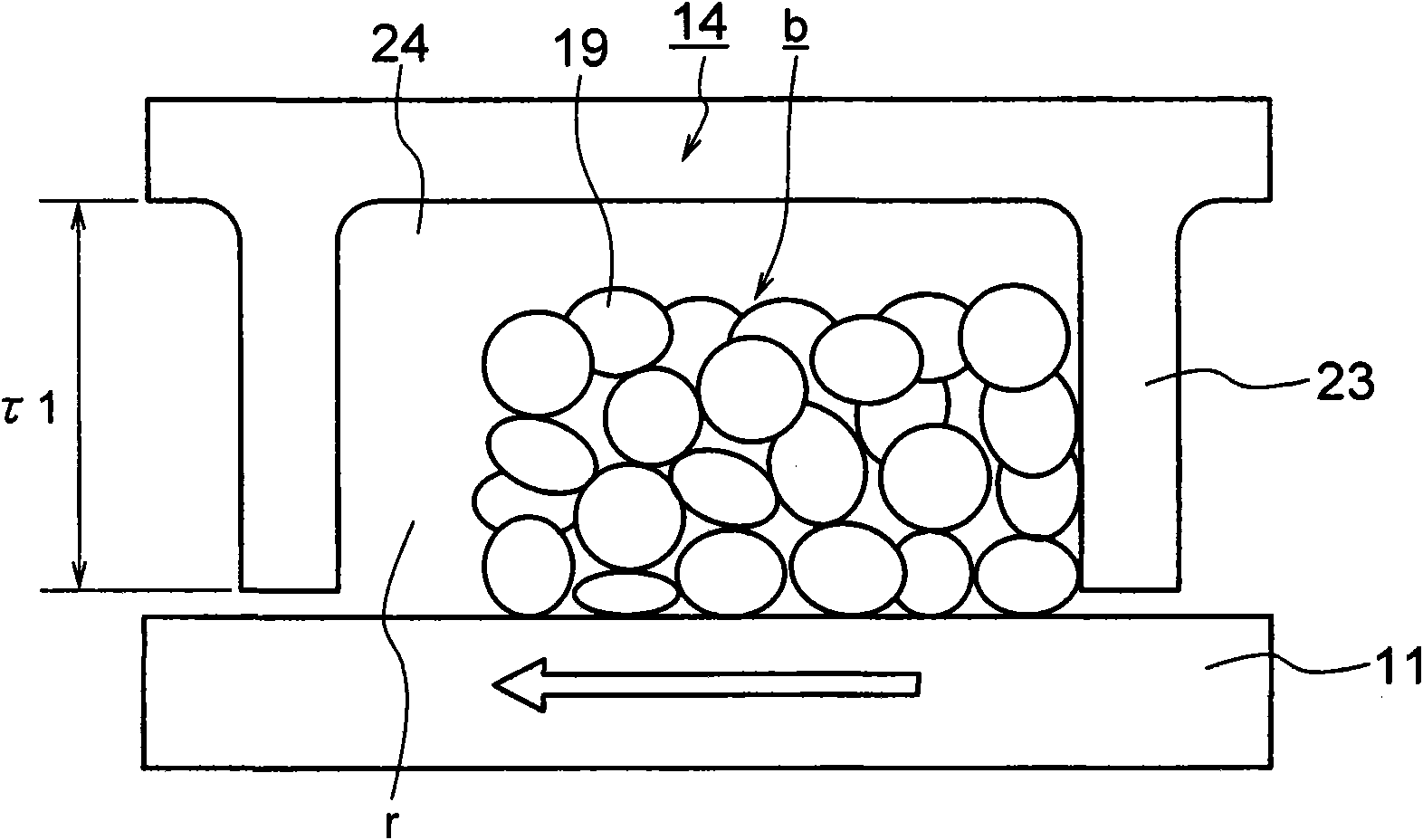
[0042] Figure 4 It is a conceptual diagram showing the main part of the injection device according to the first embodiment of the present invention, Figure 5 It is an enlarged view showing a main part of the injection device according to the first embodiment of the present invention.

[0043] Among the figure, 31 is a coaxial screw type injection device. The injection molding machine has a mold device (not shown), a mold clamping device, and the injection device 31. The mold device includes a fixed mold as a first mold and a movable mold as a second mold. The mold clamping device includes The fixed platen of the fixed mold and the movable platen of the movable mold are installed, and the movable platen is moved forward and backward by the mold clamping cylinder to perform m...


PUM


Abstract

The axial dimension of an injector (31) is decreased, inserting/removing work of a screw (20) is facilitated, and the qualities of a molding are enhanced. The injector has a heating cylinder (17), the screw (20), and a driver. The screw (20) has a main body portion (45a), and a plasticization portion provided with flights (53) formed to project from the outer circumferential surface of the main body portion (45a). Assuming the screw stroke is S, the effective length of screw is L, and a value obtained by dividing the sum of the screw stroke S and the effective length L of screw by the screw stroke S is an index e, the index e is set to satisfy a relation 2.0<Epsilon<4.5. Even if the screw (20) is shortened, resin can be melted well. Consequently, the axial dimension of the injector (31) is decreased.

Description

technical field [0001] The invention relates to an injection device. Background technique [0002] Conventionally, in a molding machine such as an injection molding machine, resin heated and melted in a heating cylinder is injected at high pressure and filled into a cavity space of a mold device, and cooled and solidified in the cavity space, thereby enabling Get moldings. [0003] Therefore, the injection molding machine includes a mold device, a mold clamping device, and an injection device. The mold clamping device includes a fixed platen and a movable platen, and the mold clamping cylinder closes the mold device by advancing and retreating the movable platen. Molding, mold closing and mold opening. [0004] On the other hand, the injection device generally uses a coaxial screw type injection device, and includes a heating cylinder for heating and melting the resin supplied from a hopper, and an injection nozzle for injecting the molten resin, and is rotatable in the he...

Claims


Application Information

Patent Timeline
IPC IPC(8): B29C45/48
CPCB29C2945/76605B29C2945/76173B29C2945/76354B29C2945/76331B29C2945/76832B29C45/76B29C45/60B29C2945/76809B29C2945/76003
Inventor 丸本洋嗣竹内滋鹫田公平后藤大辅神谷宗克
Owner SUMITOMO HEAVY IND LTD
Why Eureka
Try Eureka