Housing for a centrifugal compressor

A compressor and radial flow technology, applied in the field of radial compressor casing, can solve problems such as damaged components

Active Publication Date: 2010-11-24
BAYERISCHE MOTOREN WERKE AG
View PDF1 Cites 10 Cited by
  • Summary
  • Abstract
  • Description
  • Claims
  • Application Information

AI Technical Summary

Problems solved by technology

Due to the high speed of the impeller of the turbocharger, there is the risk that, in the event of a compressor impeller being damaged, metal fragments will pass through the casing of the compressor and damage components in the nacelle of the internal combustion engine

Method used


Image

  • Housing for a centrifugal compressor
  • Housing for a centrifugal compressor

Examples


Embodiment Construction

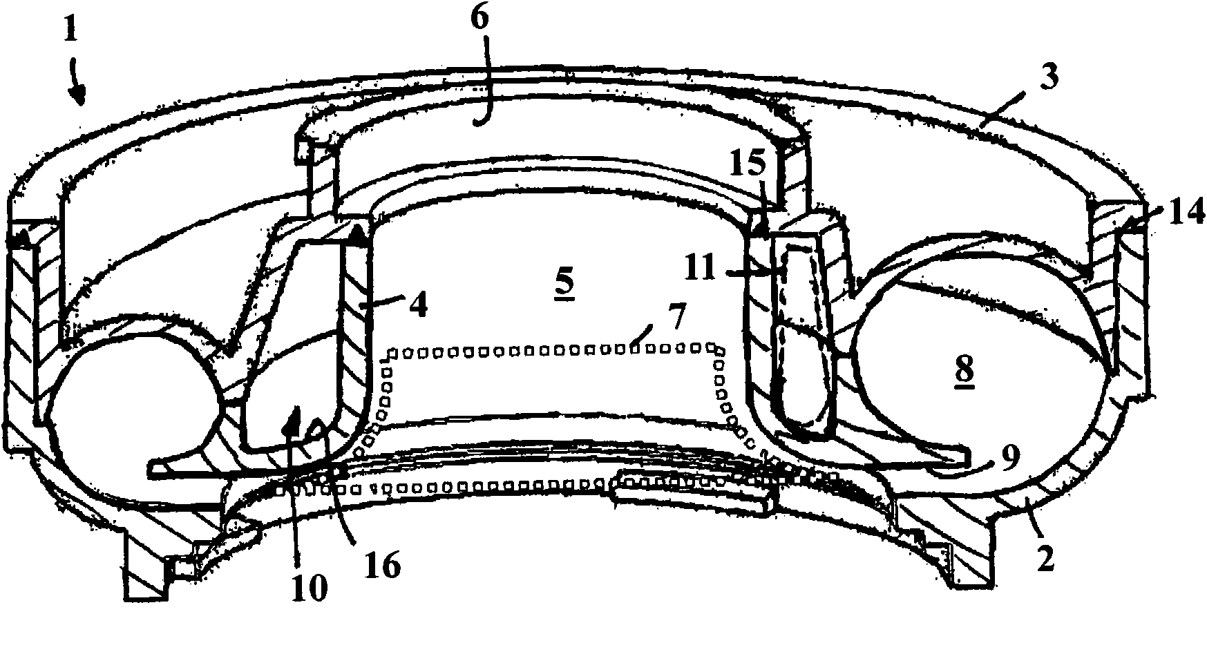
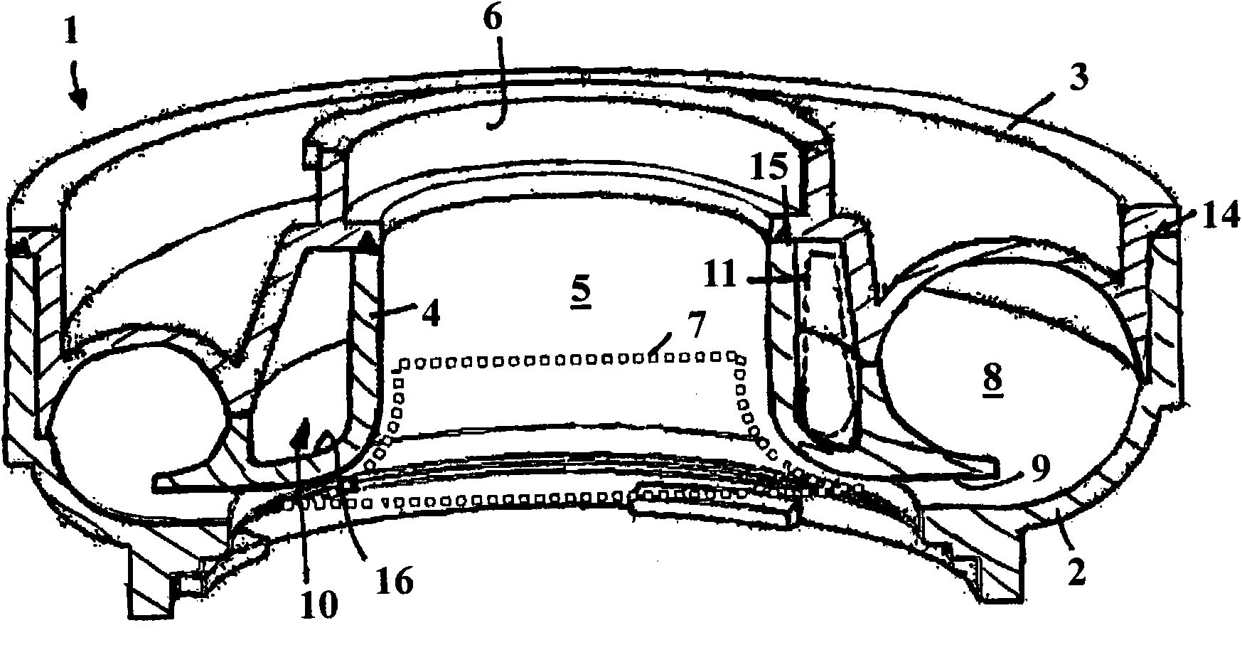
[0017] The illustrated housing 1 for a radial compressor is a component of an exhaust gas turbocharger of an internal combustion engine, in which the exhaust gas of the internal combustion engine drives a turbine wheel connected in a rotationally fixed manner to a compressor wheel, which The impeller is rotatably supported in the casing 1 . Through the rotation of the compressor wheel, the combustion air is sucked in in the suction section and compressed to a higher charge pressure, at which point the combustion air is supplied to the cylinders of the internal combustion engine.

[0018] The housing 1 is constructed in three parts and comprises a compressor rear wall 2, a compressor front 3 and inside a support shell 4 which delimits a compressor wheel accommodation space for accommodating and supporting the compressor wheel 5. The compressor wheel is provided with the reference numeral 7 in this exemplary embodiment and is shown only implicitly in dashed lines. The combustio...


PUM


Abstract

The housing for a centrifugal compressor consists of at least two plastic housing parts for accommodating a compressor wheel and for defining a helical compressor duct, an annular space being formed in the housing between the compressor wheel accommodating compartment and the compressor duct, said annular space encircling the compressor wheel and at least one stabilizing element being introduced into it.

Description

technical field [0001] The invention relates to a housing for a radial compressor according to the preamble of claim 1 . Background technique [0002] In document DE 103 14 209 B3 a radial compressor as part of an exhaust gas turbocharger is described, which consists of two shell-like housing parts injection-moulded from thermosetting plastic material Assemble together. This material has a relatively high density, so that there is no weight advantage over other common supercharger housings made of metal. In document DE 103 14 209 B3 an attempt was made to counteract the greater weight by introducing chamber-shaped recesses into one of the housing parts, which are separated from each other by a partition wall and substantially concentrically Extends around the axis of the inlet. [0003] The housing parts are glued together, but this entails relatively high production costs. Furthermore, thermosetting plastics are distinguished as materials by relatively high brittleness...

Claims


Application Information

Patent Timeline
Patent Type & Authority Applications(China)
IPC IPC(8): F04D29/02F04D29/42F04D29/44B29C65/54
CPCB29C65/08B29K2081/04F04D29/4206B29C66/1142B29L2031/7496F04D29/023B29C66/545F04D29/441B29C66/12445B29K2101/12B29C66/112B29C66/114B29C66/1282B29C66/12841B29C66/543B29C66/73921F01D21/045F05D2220/40F05D2300/43B29C66/71
Inventor 简·维尔修伊斯H·希克S·威尔德
Owner BAYERISCHE MOTOREN WERKE AG
Why Eureka
Try Eureka