Novel dust-collecting barrel for dust collector

A technology for dust collection buckets and vacuum cleaners, applied in suction filters and other directions, can solve the problems affecting the widespread popularity of vacuum cleaner products and market application prospects, reducing user experience of product use, and high price of stepper motors, so as to promote widespread popularity and market application prospects. , Significant production practical significance, the effect of enhancing the experience of product use

Inactive Publication Date: 2010-12-01
LG ELECTRONICS (TIANJIN) APPLIANCES CO LTD
View PDF0 Cites 15 Cited by
  • Summary
  • Abstract
  • Description
  • Claims
  • Application Information

AI Technical Summary

Problems solved by technology

[0008] However, the above-mentioned compression piece of the dust bin in the dust bin of the vacuum cleaner needs to be driven by a stepping motor, which leads to a large power consumption of the vacuum cleaner product, greatly increases the daily use cost of the vacuum cleaner user, and seriously reduces the user's product experience. , and because the price of the stepping motor is relatively high, the cost of the motor occupies a large proportion in the manufacturing cost of the entire dust collecting bucket, which makes the current manufacturing cost of the dust collecting bucket relatively high, which seriously affects the widespread popularization and market application prospects of vacuum cleaner products
[0009] In addition, the above-mentioned compression sheet 3 pushes the dust to the vicinity of the fixed compression plate 100 for unilateral compression, and it is easy to form dust dead spots near the fixed compression plate 100, which affects the cleaning of dust in the dust collection bin 1.

Method used


Image

  • Novel dust-collecting barrel for dust collector
  • Novel dust-collecting barrel for dust collector
  • Novel dust-collecting barrel for dust collector

Examples


Embodiment Construction

[0034] In order to enable those skilled in the art to better understand the solution of the present invention, the present invention will be further described in detail below in conjunction with the accompanying drawings and embodiments.

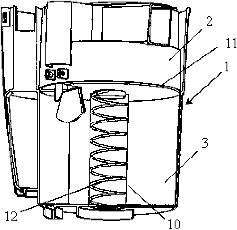
[0035] image 3 It is a schematic diagram of the structure when the compression plate of the dust bin in the dust bin of a novel vacuum cleaner provided by the present invention is in a normal free state, Figure 4 for image 3 Shown is a schematic diagram of the structure of the compression plate of the dust bin in the dust bin of the novel vacuum cleaner of the present invention when it is in a state of dust compression.

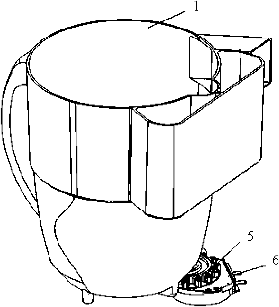
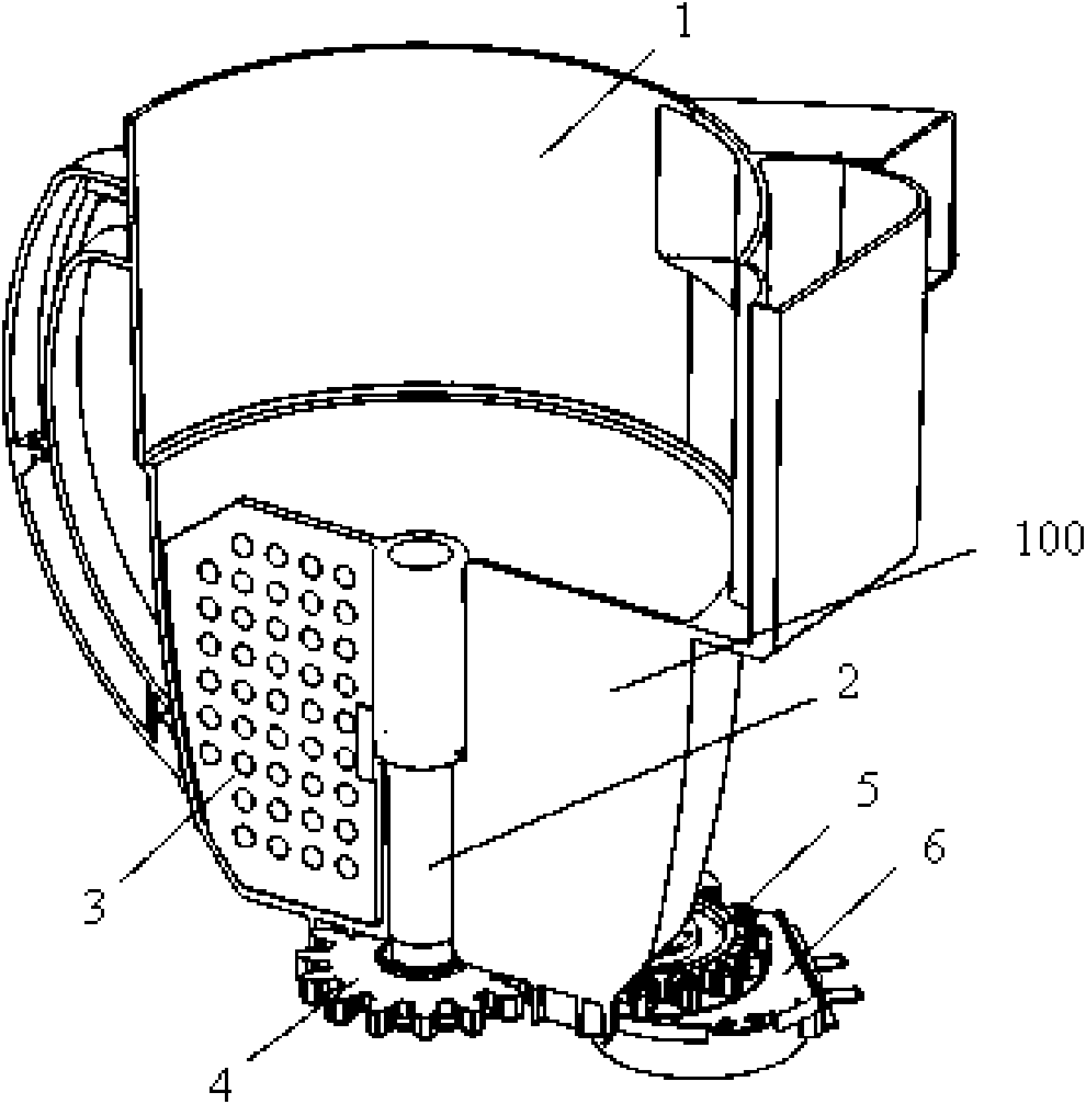
[0036] see image 3 , Figure 4, the present invention provides a new type of vacuum cleaner dust collection bucket, the dust collection bucket includes a dust collection bucket body 1, the upper opening of the dust collection bucket body 1 is provided with a cyclone separator 2, and the bottom of the cyclone separato...


PUM


Abstract

The invention discloses a novel dust-collecting barrel for a dust collector. The novel dust-collecting barrel for the dust collector comprises a dust-collecting barrel body, wherein a cyclone separator is arranged on an opening on the upper part of the dust-collecting barrel body; a dust-collecting bin is arranged below the cyclone separator; the cyclone separator is communicated with the dust-collecting bin; an extension tube is arranged in the center of the bottom of the dust-collecting bin; a horizontal compression plate is arranged on the top of the extension tube; an opening is formed at the bottom of the extension tube and is hermetically connected with a suction pipeline; the suction pipeline is communicated with a space where a main motor of the dust collector is; a return spring is arranged in the extension tube; the lower end of the return spring is fixedly connected with the bottom of the dust-collecting bin; and the upper end of the return spring is fixed on the compression plate. In the novel dust-collecting barrel for the dust collector disclosed by the invention, the compression plate can compress dust in the dust-collecting bin without the motor separately and the dust-collecting bin does not have any dead angle and is not scaled, so the electric energy is saved, the production cost and the daily use cost of the dust collector are reduced, and the product using experience of users is enhanced.

Description

technical field [0001] The invention relates to the technical field of mechanical dust removal, in particular to a novel dust collecting barrel of a vacuum cleaner. Background technique [0002] Generally, a vacuum cleaner is a device that uses a vacuum to generate suction to inhale air, make the air flow through various filters, filter foreign objects in the air, and clean the room. [0003] Generally speaking, a vacuum cleaner mainly includes a suction device and a suction pipeline. The suction device mainly formed by a motor and a fan is arranged in the body. The suction pipeline includes a suction head and a suction pipe. The suction head has a downward opening. The suction port communicates with the air inlet of the fan inside the body through the telescopic pipe and the flexible pipe of the suction pipe. When the vacuum cleaner is running, the motor drives the impeller of the fan to rotate at a high speed, exhausting the air in the vacuum cleaner, forming an instantan...

Claims


Application Information

Patent Timeline
Patent Type & Authority Applications(China)
IPC IPC(8): A47L9/16
Inventor 陈晓
Owner LG ELECTRONICS (TIANJIN) APPLIANCES CO LTD
Why Eureka
Try Eureka