Clamp structure for milling positioning reference plane on glass die blank

A glass mold and positioning datum technology, used in positioning devices, clamping, milling machine equipment, etc., can solve problems such as unheard of successful reports in the industry, and achieve the goal of eliminating damage, accurate and consistent positioning datum planes, and guaranteed thickness. Effect

Active Publication Date: 2012-02-29
CHANGSHU JIANHUA MOLD TECH
View PDF0 Cites 58 Cited by
  • Summary
  • Abstract
  • Description
  • Claims
  • Application Information

AI Technical Summary

Problems solved by technology

But so far, no corresponding technical revelation has been seen in both patent literature and non-patent literature, and there have been no reports of success in the industry.

Method used


Image

  • Clamp structure for milling positioning reference plane on glass die blank
  • Clamp structure for milling positioning reference plane on glass die blank
  • Clamp structure for milling positioning reference plane on glass die blank

Examples


Embodiment Construction

[0021] In order to enable the examiners of the patent office, especially the public, to understand the technical essence and beneficial effects of the present invention more clearly, the applicant will describe in detail below in conjunction with the accompanying drawings in the form of embodiments, but none of the descriptions of the embodiments is a description of the present invention. Restriction of the inventive solution, any equivalent transformation made according to the concept of the present invention which is only in form but not in substance shall be regarded as the scope of the technical solution of the present invention.

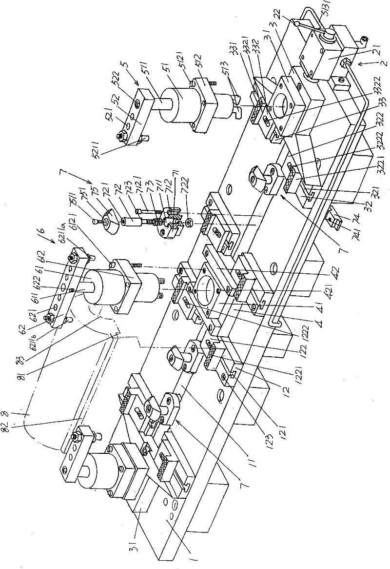
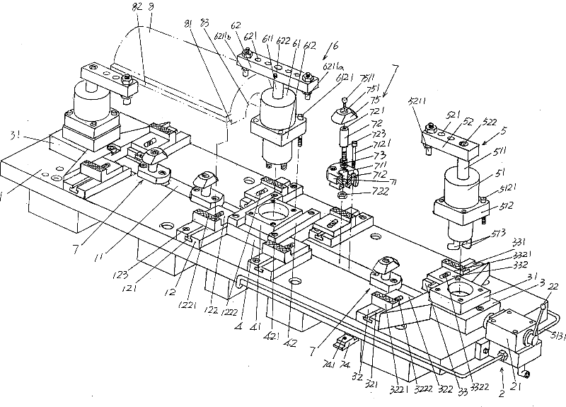
[0022] Please see figure 1 , provides a rectangular parallelepiped and plate-shaped base 1, when using the present invention, the base 1 is installed and fixed on a bed such as a milling machine. As shown in the figure, a reference seat adjustment groove 11 penetrating from one end to the other end is provided at the center of the base 1 in the...


PUM


Abstract

The invention provides a clamp structure for milling a positioning reference plane on a glass die blank and belongs to an auxiliary facility for processing a glass die. The structure comprises a base, an acting cylinder control device, at least one adjusting seat, a fixed seat, a first die blank back side pressing device, a second die blank back side pressing device and at least one pair of die blank die cavity supporting devices, wherein a reference seat adjusting groove which is penetrated from one end to the other end is formed at a middle position in the width direction of the base; the acting cylinder control device is fixed at one end of the base; the at least one adjusting seat is arranged on the base and in sliding fit with the reference seat adjusting groove; the fixed seat is fixedly arranged on the base and corresponds to the adjusting seat; the first die blank back side pressing device is arranged on the adjusting seat and connected with the acting cylinder control device;the second die blank back side pressing device is arranged on the fixed seat and connected with the acting cylinder control device; and the at least one pair of die blank die cavity supporting devices is arranged on the reference seat adjusting groove in a sliding way and positioned between the adjusting seat and the fixed seat. The structure has the advantages of guaranteeing the accuracy of subsequent processing and ensuring the thickness of a high-quality compact layer of the die cavity.

Description

technical field [0001] The invention belongs to the technical field of auxiliary facilities for glass mold processing, and in particular relates to a fixture structure for milling a positioning reference plane on a glass mold blank. Background technique [0002] Fixtures, also known as tooling fixtures, play a very important role in the production of industrial products, and the production of glass molds is no exception. The so-called tooling fixture refers to the special equipment or tools that clamp or position the workpiece in machining to meet certain process requirements. Fixtures usually need to meet the requirements of no interference during product production (processing), accurate and reliable positioning, and convenient operation. Since the tooling fixture has the exclusive characteristics of manufacturing a certain product or a certain type of product, it is highly targeted and has a low degree of versatility. It is often designed and manufactured by the manufact...

Claims


Application Information

Patent Timeline
Patent Type & Authority Patents(China)
IPC IPC(8): B23Q3/06B23C3/00
Inventor 马建华马连保方朝辉
Owner CHANGSHU JIANHUA MOLD TECH
Why Eureka
Try Eureka