Gear cutting machine

A technology for gear cutting machines and grinding tools, which is applied in the directions of gear cutting machines, gear teeth, mechanical equipment, etc., to avoid different positions and shorten the time spent

Inactive Publication Date: 2010-12-01
LIEBHERR VERZAHNTECHNIK GMBH
View PDF2 Cites 17 Cited by
  • Summary
  • Abstract
  • Description
  • Claims
  • Application Information

AI Technical Summary

Problems solved by technology

The disadvantage of this invention is that the dressing device can only be used for the inner grinding head, and the grinding angle of the grinding disc must be returned to the basic position for dressing during the grinding process

Method used


Image

  • Gear cutting machine
  • Gear cutting machine
  • Gear cutting machine

Examples


Embodiment Construction

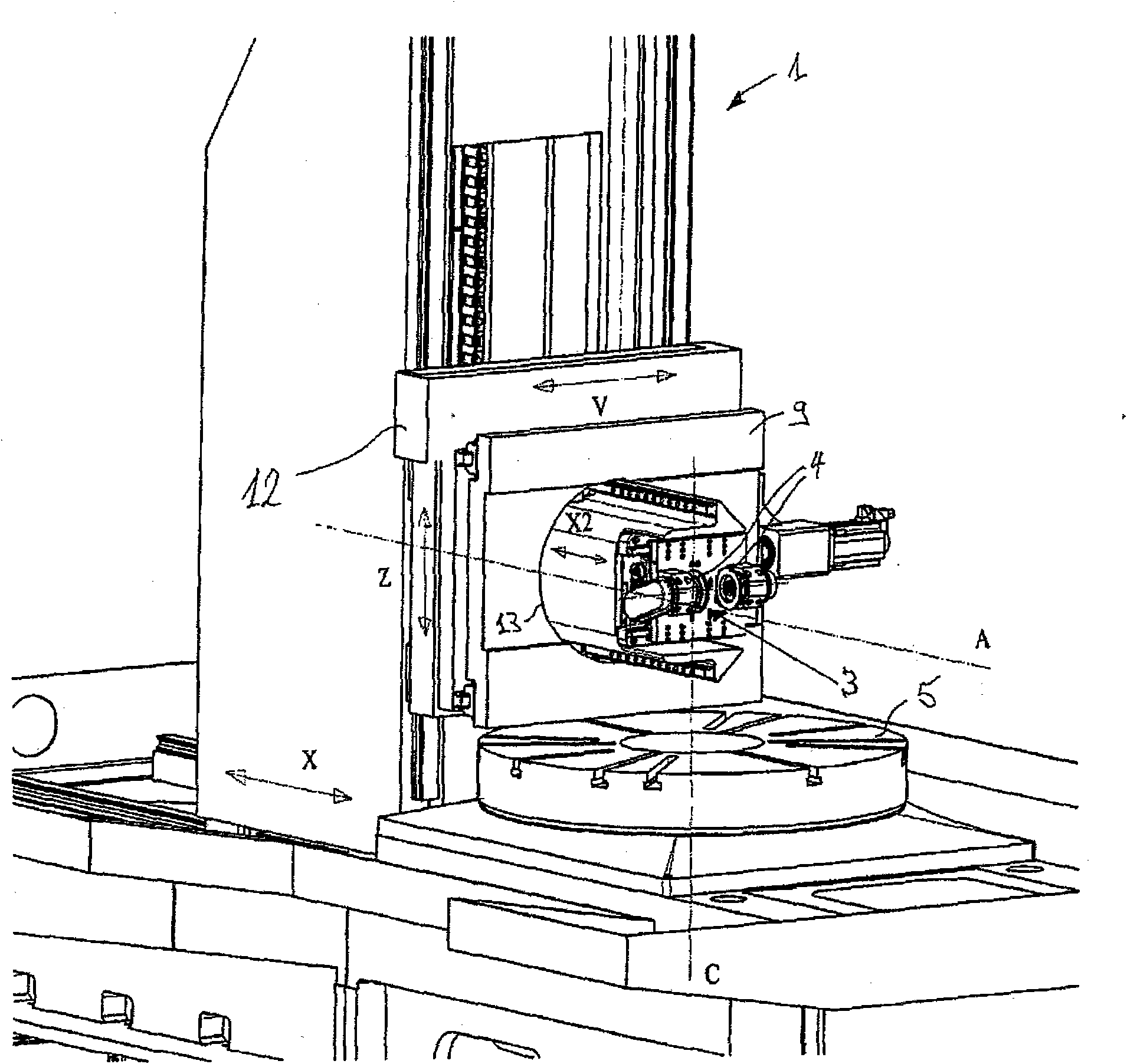
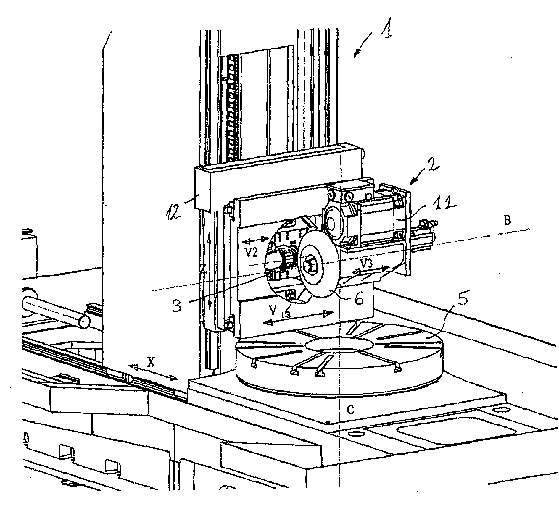
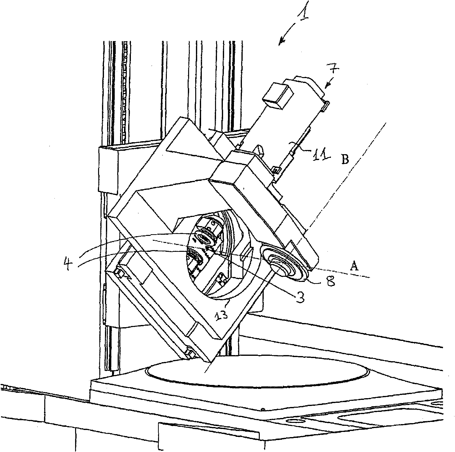
[0033] will refer to figure 1 The general design of the gear cutting machine is described in more detail. It has a machine table 5 for mounting a tool receiver and on which a workpiece can be clamped. In this respect, the machine table 5 is rotatable about an axis C, which is advantageously positioned in a vertical manner. As an alternative, however, horizontally positioned workpiece receivers can also be used. Gear cutting machine 1 also has a tool for mounting processing heads 2, 7 (respectively see figure 2 and image 3 ) of one or more mounting surfaces 9. An external grinding head 2 for machining the outer contour of a workpiece or an inner grinding head 7 for machining the inner contour of another workpiece can be mounted on the gear cutting machine 1 (see respectively figure 2 and image 3 ). One or more grinding tools 6 , 8 can be clamped on the respective machining head 2 , 7 . In this respect, the grinding tools 6 , 8 are arranged to be rotated by the motor...


PUM


Abstract

The invention relates to a gear cutting machine for the grinding of external profiles and / or internal profiles of workpieces having at least one machining head which can be rotated about an axis and which has a grinding tool, and having a dressing unit. In accordance with the invention, the dressing unit is supported in the region of the pivot axis of the machining head such that it is pivotable about the common pivot axis together with the machining head and such that it can be moved along the pivot axis toward the grinding tool to be dressed.

Description

technical field [0001] The invention relates to a gear cutting machine for grinding the inner or outer contour of a workpiece, the gear cutting machine having a machining head and a dressing unit, in particular a shared dressing unit, the machining head being arranged on a pivotable mounting surface and having a There is a grinding tool, the dressing unit has a grinding tool for dressing an installed external or internal grinding head. For example, grinding worms or grinding discs can be used here as grinding tools. [0002] In order to achieve or maintain a precisely balanced running and correct geometry of the grinding tool, the grinding tool must be shaped and periodically sharpened by means of dressing. In addition, dressing is used to reshape and / or calibrate the grinding tool. It also has the purpose of drawing impurities and the already dulled grain layer out of the grinding wheel and thereby exposing the sharp grains. In this respect, it is desirable that the dressi...

Claims


Application Information

Patent Timeline
Patent Type & Authority Applications(China)
IPC IPC(8): B24B53/06B24B53/08B23F23/12B23F1/02
CPCB23F23/1225B24B53/075B24B53/053B23F1/02
Inventor 阿洛伊斯·蒙特
Owner LIEBHERR VERZAHNTECHNIK GMBH
Why Eureka
Try Eureka