Allocation of channels to radio transceivers

A radio transceiver and transceiver technology, applied in the field of channel allocation, can solve problems such as interference, and achieve the effect of eliminating needs and dependencies, saving labor, and avoiding inaccuracy

Inactive Publication Date: 2003-04-23
BRITISH TELECOMM PLC
View PDF1 Cites 4 Cited by
  • Summary
  • Abstract
  • Description
  • Claims
  • Application Information

AI Technical Summary

Problems solved by technology

"Adjacent channel" interference by another call using a different channel is also a problem: a call made on a channel corresponding to the 4000-4025KHZ band is susceptible to interference from a call on the adjacent band 4025-4050KHZ
Also, even if a highly accurate table is produced, it can only be maintained until the network changes

Method used


Image

  • Allocation of channels to radio transceivers
  • Allocation of channels to radio transceivers
  • Allocation of channels to radio transceivers

Examples


Embodiment Construction

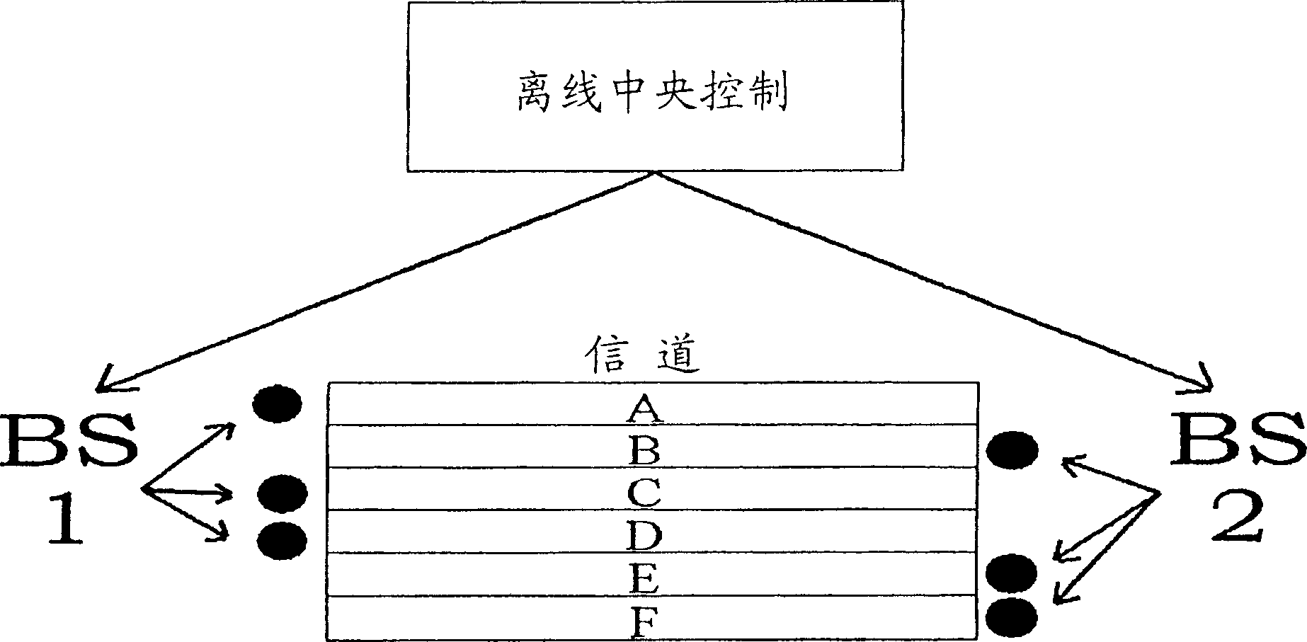
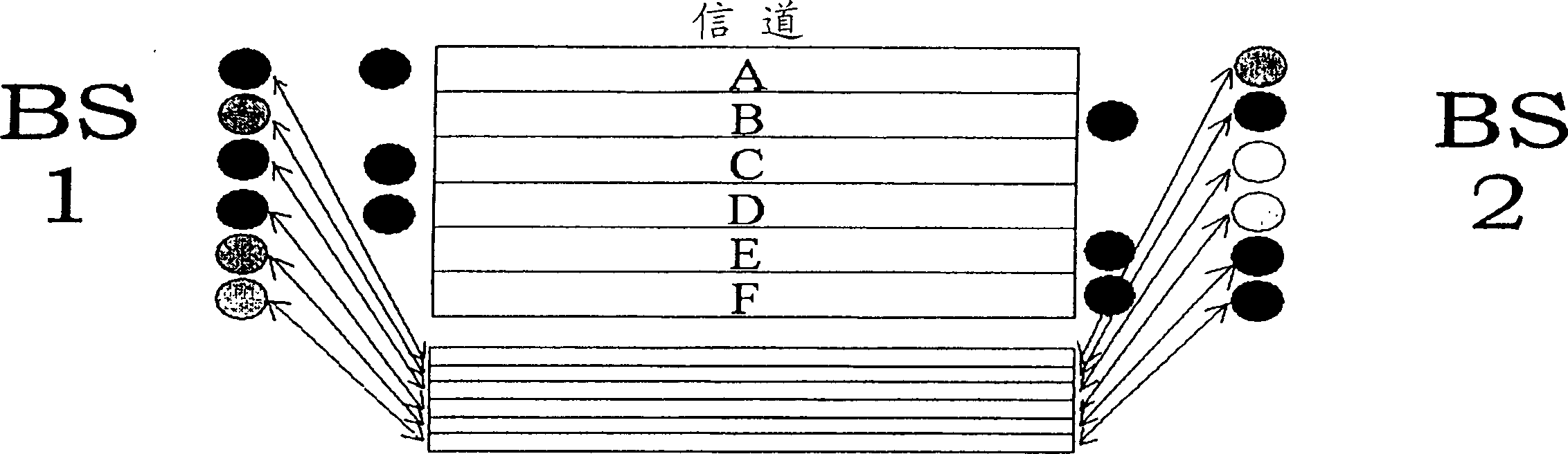
[0029] Figure 1-3 Two base transceiver stations BS1, BS2 are shown, both of which have access to six traffic channels A, B, C, D, E, F. exist figure 1 In the prior art system, a central controller determines the optimal allocation. This occurs "offline" based on interference and congestion data collected over a period of time. The best distribution is then added to the network. optimal distribution figure 1 The marks in indicate that channels A, C, and D are assigned to BS1, and channels B, E, and F are assigned to BS2.

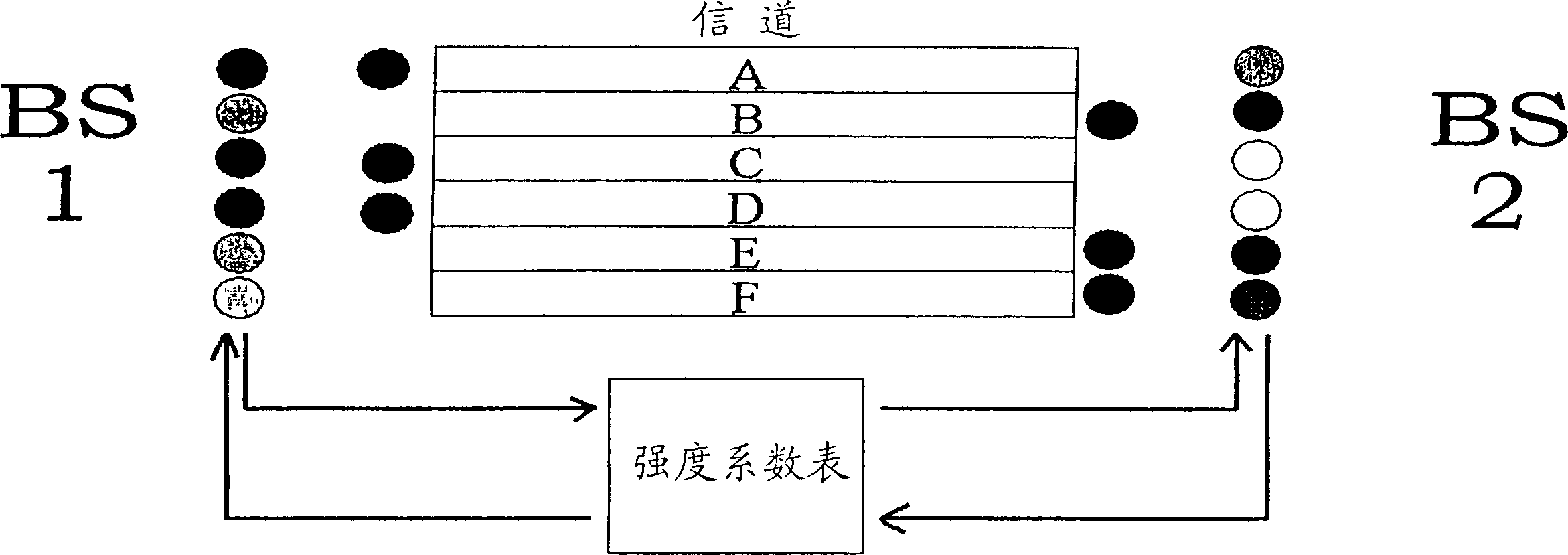
[0030] figure 2 The allocation method of the prior art system disclosed in WO099 / 56488 is shown. Each base station maintains a set of priority values, defined by figure 2 The six shaded channel markers represent the middle grade. The base station communicates these priority values ​​to other base stations in the network, which multiply them by the relevant coefficients in a globally recognized table of strength coefficients. The resulting value is...


PUM


Abstract

Each base station in a network has an antenna (1) which is connected in the conventional way to a transceiver (2) for handling normal call traffic on one or more radio channels. In addition there is another transmitter (3) which transmits a test signal on each of several test channels, one for each radio channel available for use by the main transceiver (2). The transceiver also has a receiver (4) for detecting the test channels. The system is controlled by a timer (5) which ensures that the transmitter (3) and receiver (4) do not operate at the same time. The receive times may be random, or may be co-ordinated between individual base stations. When the receiver is in operation, it will detect transmissions of the test signals from other base stations. The signal strength is measured (measurement system (6)) and the result is used by a control system (7) to determine a preference value for each channel: the stronger the signal detected, the lower the preference value. The preference value is used to control an amplifier system (8) which controls the signal strength of each channel transmitted by the transmitter (3). It is also used to control the traffic transceiver (2), by selecting which traffic channels are to be used in accordance with the preference values.

Description

field of invention [0001] The invention relates to channel allocation to radio transceivers in a radio network. The described embodiments are directed to fixed base stations of a cellular telephone network, but the invention can also be used in other networks of radio transmitters and / or receivers. Background technique [0002] A cellular telephone network includes a large number of fixed base transceiver stations and an even larger number of mobile handsets that communicate with the base stations over radio channels. A so-called "cell" (cell) in a cellular telephone network refers to the coverage area of ​​a single fixed radio base station. Each operator is allowed to use a limited number of radio channels, and there may not be enough channels for every telephone call in the network to be carried on a different channel. A central principle of such networks is therefore channel reuse: each channel can be operated by many base stations at any time. This introduces the poss...

Claims


Application Information

Patent Timeline
Patent Type & Authority Applications(China)
IPC IPC(8): H04B17/00H04W16/04
CPCH04W16/04
Inventor 理查德·爱德华·泰特森
Owner BRITISH TELECOMM PLC
Why Eureka
Try Eureka