Flat and thin type heat pipe

A heat pipe, a flat technology, applied in the field of flat and thin heat pipes, can solve the problems of increased thermal resistance, heat transfer heat reduction of heat pipes, and liquid delivery capacity decline, etc., to achieve good heat dissipation performance, smooth steam flow, and increase capillary force.

Inactive Publication Date: 2010-12-01
FURUI PRECISE COMPONENT (KUNSHAN) CO LTD +1
View PDF0 Cites 14 Cited by
  • Summary
  • Abstract
  • Description
  • Claims
  • Application Information

AI Technical Summary

Problems solved by technology

However, when the heat pipe is flattened, especially when it is flattened to a very thin thickness, the capillary structure is prone to deformation and disintegration, which greatly reduces its liquid delivery capacity, and the liquid delivery capacity of the entire heat pipe cannot It is supplemented by other means, resulting in a significant decrease in the maximum heat transfer of the heat pipe and an increase in thermal resistance
At the same time, because the thickness of the heat pipe is very thin, the use of the existing capillary structure will make the steam channel inside the heat pipe very narrow, and the steam cannot be transported from the evaporation section to the condensation section in time, which also leads to the maximum of the heat pipe to a large extent. A drastic drop in heat transfer

Method used


Image

  • Flat and thin type heat pipe
  • Flat and thin type heat pipe
  • Flat and thin type heat pipe

Examples


Embodiment Construction

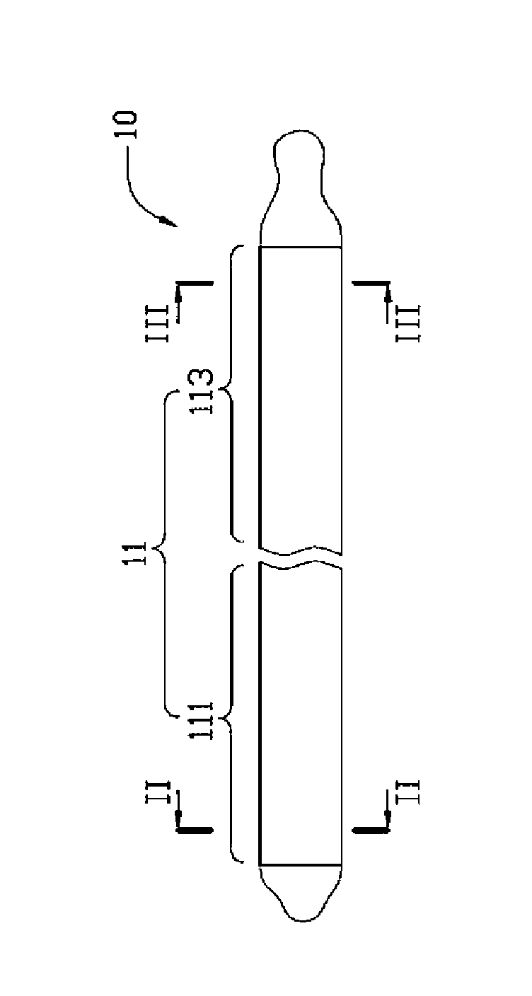
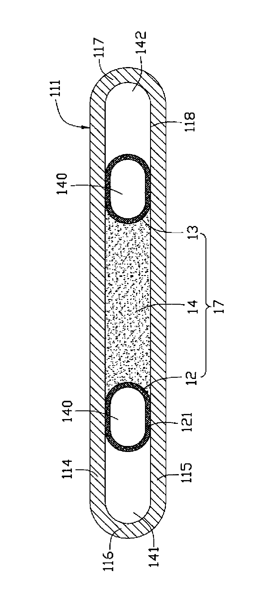
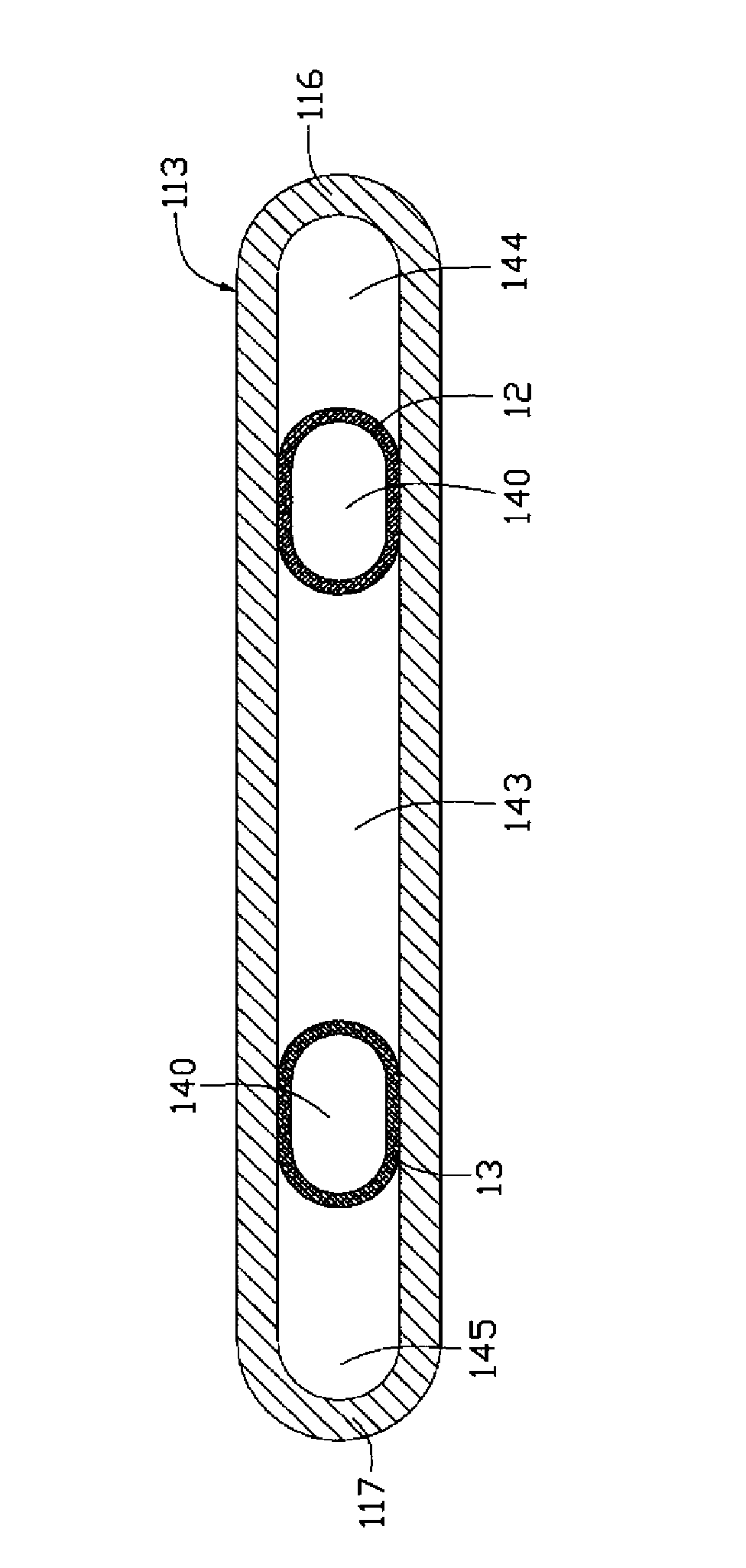
[0020] see Figure 1 to Figure 3 The flat and thin heat pipe 10 includes a hollow flat tube body 11, two first capillary structures 12, 13, a second capillary structure 14 and an appropriate amount of working medium (not shown) injected into the tube body 11.

[0021] The pipe body 11 is made of copper and other materials with good thermal conductivity, which can transfer the heat from the outside to the inside. The tube body 11 is longitudinally flat and sealed, and includes an evaporation section 111 and a condensation section 113 along its longitudinal direction. The evaporation section 111 and the condensation section 113 are respectively located at two longitudinal ends of the tube body 11 . The tube body 11 is a hollow sealed cavity formed by flattening a hollow circular tube, including a top plate 114 , a bottom plate 115 and two side plates 116 , 117 . The top plate 114 and the bottom plate 115 are parallel to each other and opposite up and down. The two side plates 1...


PUM

PropertyMeasurementUnit
thicknessaaaaaaaaaa

Abstract

The invention relates to a flat and thin type heat pipe which comprises a hollow flat pipe body and also comprises a first capillary structure and a second capillary structure which are arranged in the pipe body, wherein the pipe body comprises an evaporation section, a condensation section, a top plate and a bottom plate opposite to the top plate; the first capillary structure consists of silk threads and extends to the condensation section from the evaporation section of the pipe body; the second capillary structure is formed by sintering powder, is of a solid structure and is arranged on the evaporation section of the pipe body; the second capillary structure is connected between the top plate and the bottom plate of the pipe body; and the first capillary structure is connected with the second capillary structure at the evaporation section. Compared with the prior art, the flat and thin type heat pipe is thin, and good properties can be guaranteed, thus the flat and thin type heat pipe is suitable for electronic equipment with a narrow inner space. The invention also discloses a manufacture method of the flat and thin type heat pipe.

Description

technical field [0001] The invention relates to a heat pipe, in particular to a flat and thin heat pipe. Background technique [0002] At present, heat pipes have been widely used in electronic components with large heat generation due to their advantages of high heat transfer. When the heat pipe is working, the low-boiling-point working medium filled in the pipe body absorbs the heat generated by the heating electronic components in the evaporation part and then evaporates and vaporizes. The steam moves to the condensation part with heat and releases the heat by liquefaction and condensation , to dissipate heat from electronic components. The liquefied working medium flows back to the evaporator under the action of the capillary structure of the heat pipe wall, and continues to evaporate, vaporize, liquefy and condense, so that the working medium circulates inside the heat pipe and continuously emits the heat generated by the electronic components. [0003] Today's electr...

Claims


Application Information

Patent Timeline
Patent Type & Authority Applications(China)
IPC IPC(8): F28D15/04B23P15/26
CPCF28D15/0233B23P2700/09F28D15/046Y10T29/49353
Inventor 刘悦代升亮刘金朋周生国吴声麟罗友梁
Owner FURUI PRECISE COMPONENT (KUNSHAN) CO LTD
Why Eureka
Try Eureka