
Fiber grating clamp-type helical line slow-wave structure

A fiber grating and slow-wave structure technology, which is applied in the field of microwave electronics, can solve problems such as the inability to obtain temperature distribution, and achieve the effect of suppressing back-wave oscillation

Active Publication Date: 2011-09-07
SOUTHEAST UNIV
View PDF0 Cites 0 Cited by
  • Summary
  • Abstract
  • Description
  • Claims
  • Application Information

AI Technical Summary

Problems solved by technology

Both of these methods cannot obtain accurate temperature distribution

Method used


Image

  • Fiber grating clamp-type helical line slow-wave structure
  • Fiber grating clamp-type helical line slow-wave structure
  • Fiber grating clamp-type helical line slow-wave structure

Examples


Embodiment Construction

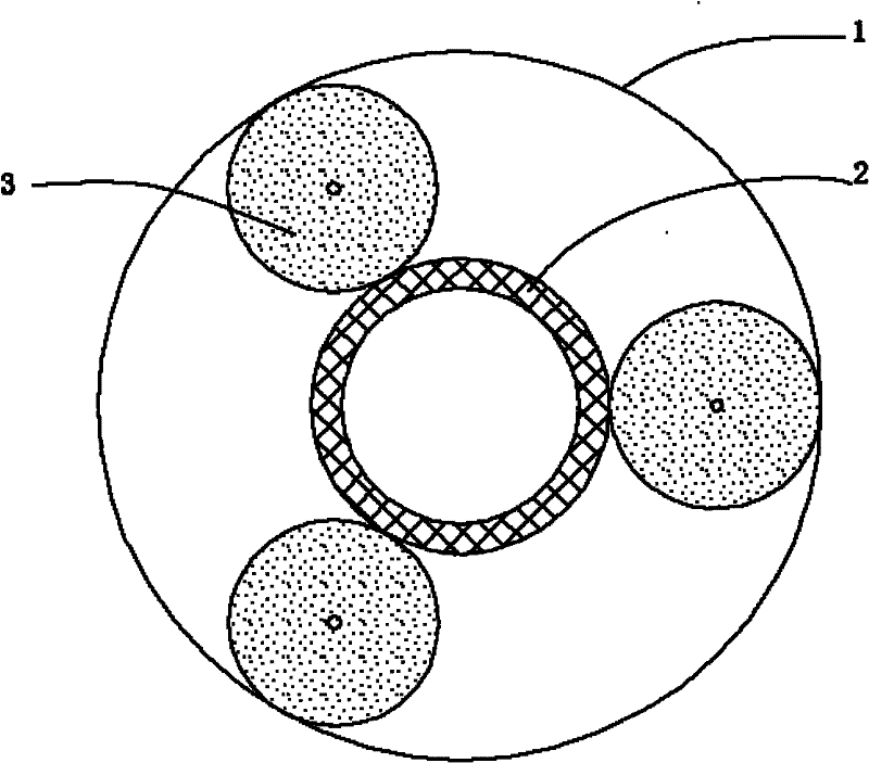
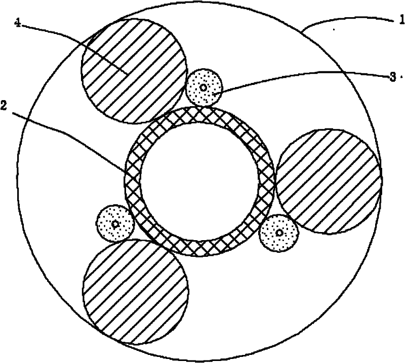
[0023] The fiber Bragg grating clamping type helical slow wave structure of the present invention uses Bragg fiber grating as the clamping rod material, that is, a helix 2 is arranged on the axis of the shell 1, and a fiber grating 3 is arranged between the shell and the helix .

[0024] Fiber Bragg Gratings are circular clamping rods.

[0025] A carbon film is plated on the fiber grating to make a distributed attenuator to suppress the return wave oscillation of the traveling wave tube.

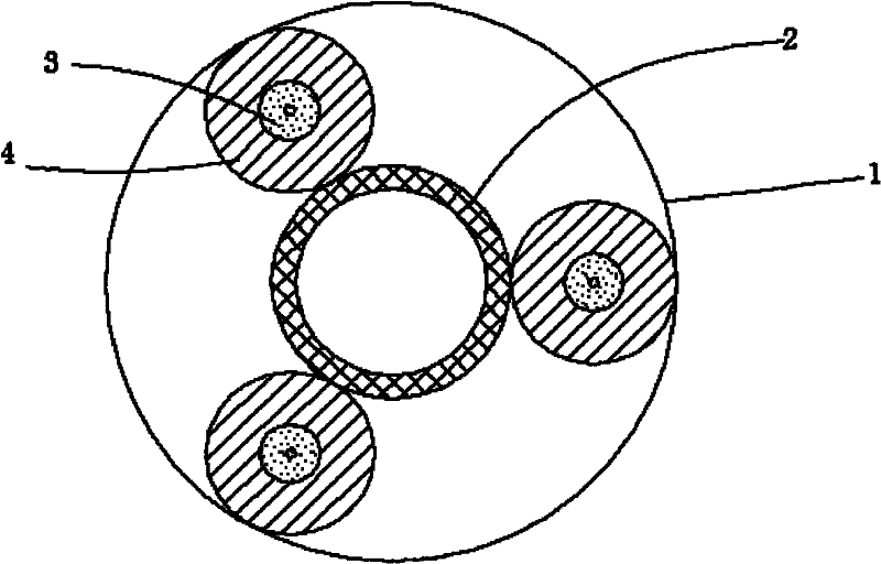
[0026] A circular clamping rod or a fan-shaped clamping rod with a distributed attenuator is arranged outside the fiber grating cladding.

[0027] Place the fiber grating next to the circular clamping rod or fan-shaped clamping rod, and fix it with glue.

[0028] In order to realize the distributed measurement of the temperature of the helix, the structure uses Bragg fiber grating as the clamping rod material, that is, the helix 2 is arranged on the axis of the shell 1, and the optical fib...


PUM


Abstract

The present invention provides a helical line slow-wave structure of a fiber grating clamping rod, relating to a helical line traveling wave tube clamp-type slow-wave structure, comprising a tube housing (1), a helical line (2), a fiber grating (3) and a medium clamping rod (4). The fiber grating (3) in the helical line slow-wave structure can be arranged in three ways; the first one is arrangingthe fiber grating (3) beside a common round ceramic medium clamping rod (4) or a section ceramic medium clamping rod (5), and fixing through spot gluing; the second one is taking the fiber grating (3) directly as a round clamping rod to replace the traditional ceramic medium clamping rod; and the third one is coating a medium layer at a coat layer of the fiber grating (3) to prepare the round clamping rod (4) and the section clamping rod (5). The fiber grating is used as the material of the clamping rod, so as to realize the distribution measurement of the temperature of the traveling wave tube helical lines, and provide the test data for the analysis of the working stability of the traveling wave tube; and the outer side of the fiber grating is coated with a carbon membrane to prepare a distribution attenuator to eliminate the back wave vibration of the traveling wave tube.

Description

technical field [0001] The invention relates to a helical traveling wave tube fiber grating clamping type slow wave structure, which belongs to the field of microwave electronics. Background technique [0002] High-power traveling wave tubes are the core components of airborne, shipborne, spaceborne radar and other instruments, and are widely used in military and civilian applications. The slow-wave system is a key component that determines the performance of the TWT, and a good slow-wave structure plays an important role in improving the beam-beam interaction. Among the various characteristics of the helical TWT, the thermal characteristic is a very important index, which is the main factor that determines the average output power of the TWT and directly affects the stability and reliability of the TWT. [0003] When the traveling wave tube is in normal operation, the temperature around the helix is ​​very high, and the temperature change will have a great impact on the wo...

Claims


Application Information

Patent Timeline
Patent Type & Authority Patents(China)
IPC IPC(8): H01J23/26
Inventor 孙小菡陈明芳印中举柏宁丰樊鹤红
Owner SOUTHEAST UNIV
Learn More