
Rhombic meander line slow wave structure loaded on basis of multiple dielectric rod supporting ridges

A technology of slow wave structure and dielectric rod, which is applied in the cooling method of discharge tube, transit time type electronic tube, electrical components, etc., can solve the problems of heavy workload and cumbersome strip line process.

Active Publication Date: 2022-03-18
UNIV OF ELECTRONICS SCI & TECH OF CHINA
View PDF9 Cites 0 Cited by
  • Summary
  • Abstract
  • Description
  • Claims
  • Application Information

AI Technical Summary

Problems solved by technology

However, the process of designing stripline lines with different period lengths is cumbersome and requires a lot of work

Method used


Image

  • Rhombic meander line slow wave structure loaded on basis of multiple dielectric rod supporting ridges
  • Rhombic meander line slow wave structure loaded on basis of multiple dielectric rod supporting ridges
  • Rhombic meander line slow wave structure loaded on basis of multiple dielectric rod supporting ridges

Examples


Embodiment Construction

[0036] Specific embodiments of the present invention will be described below in conjunction with the accompanying drawings, so that those skilled in the art can better understand the present invention. It should be noted that in the following description, when detailed descriptions of known functions and designs may dilute the main content of the present invention, these descriptions will be omitted here.

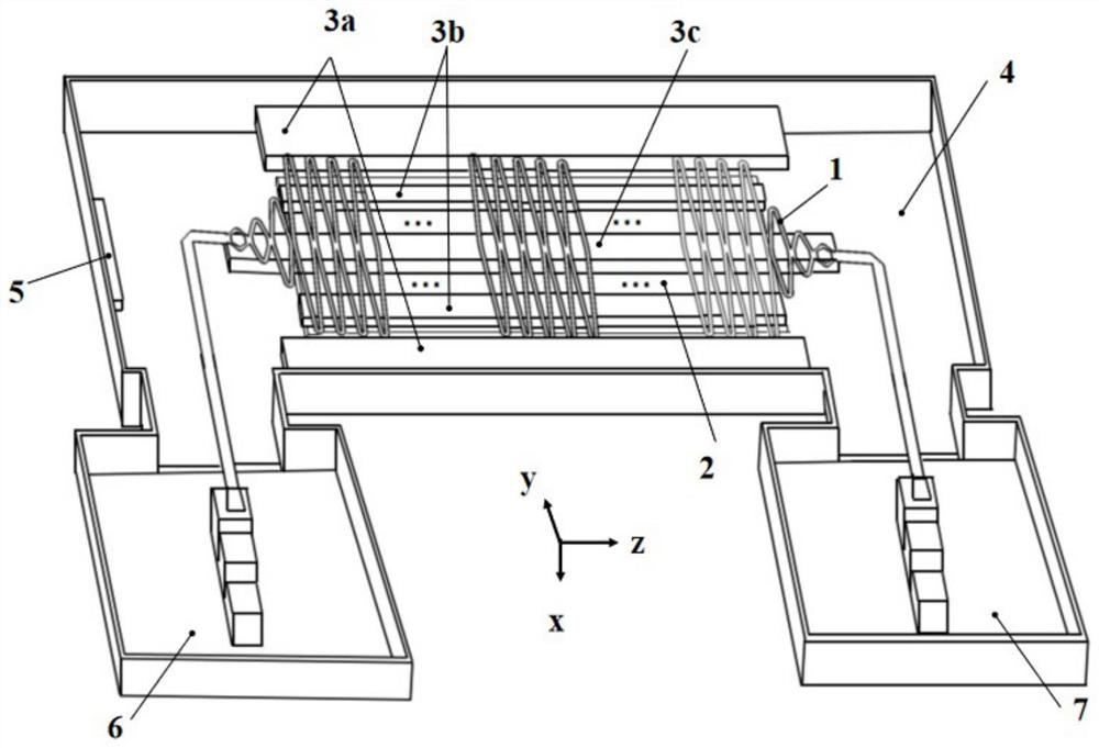
[0037] figure 2 It is a structural schematic diagram of a specific embodiment of the present invention based on a plurality of dielectric rod support ridges loading a rhombic zigzag line slow wave structure.

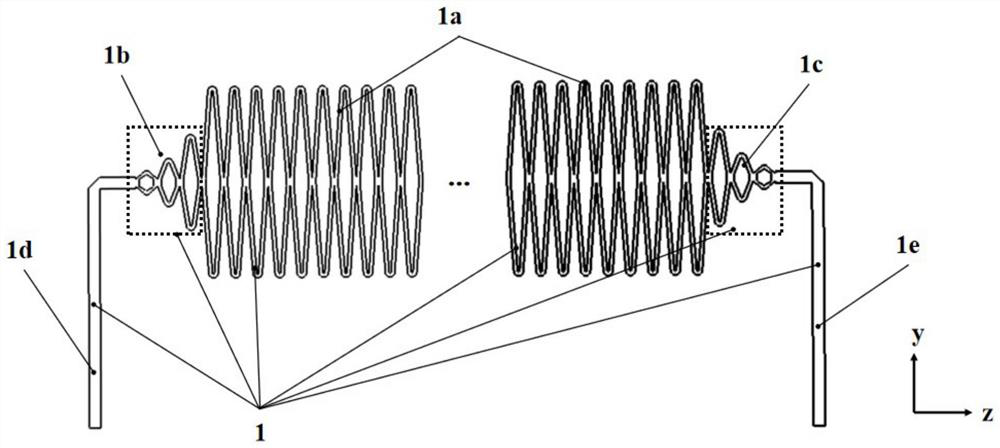
[0038] In this example, if figure 2 As shown, the present invention is based on a plurality of dielectric rod support ridges loading rhombic zigzag line slow wave structure, including a metal slow wave line 1, multiple metal ridges 2, clamping rods 3a on both sides, and multiple (three) bottom side clamping rods. Rods 3b, 3c, metal casing 4, sheet cathode 5, micro...


PUM


Abstract

The invention discloses a diamond meander line slow wave structure loaded on the basis of a plurality of dielectric rod supporting ridges, which is characterized in that on the basis of the existing diamond meander line slow wave structure clamped by dielectric rods, a metal ridge is carved on the lower side surface in a metal shell to weaken the dispersion intensity of the slow wave structure, so that the working frequency and the working bandwidth of a traveling wave tube are improved, and the service life of the traveling wave tube is prolonged. Meanwhile, the working voltage can be effectively reduced, and the efficiency of the traveling wave tube is improved; meanwhile, the clamping rods on the two sides of the metal slow-wave line are embedded in the left side and the right side of the electron beam wide edge in the metal shell, and the lower ends of the multiple clamping rods on the bottom side for supporting the metal slow-wave line are clamped in grooves formed between the adjacent metal ridges, so that the structure can be more stable, and the heat dissipation problem of the slow-wave structure is effectively solved. Besides, the phase velocity change of the structure is realized by dividing the thickness of the two bottom side clamping rods located on the outermost sides of the left and right sides of the wide edge of the electron beam into a plurality of sections along the transmission direction of the electron beam and increasing the thickness section by section, so that the backward wave oscillation is inhibited, and the processing difficulty is reduced.

Description

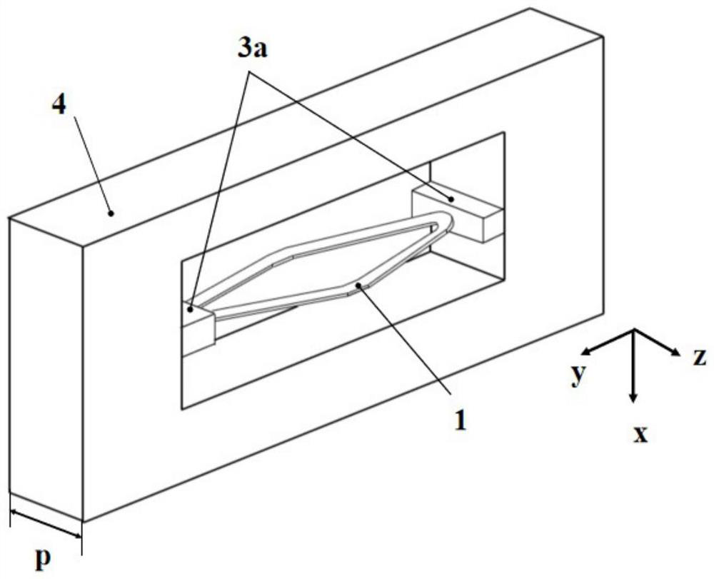
technical field [0001] The invention belongs to the technical field of strip-shaped injection plane slow-wave structures, and more specifically relates to a rhombic zigzag-line slow-wave structure loaded on the basis of multiple dielectric rod support ridges, which is used for traveling wave tube amplifiers. Background technique [0002] Traveling wave tube is an important vacuum electronic device, which has a wide range of applications in various fields. The core part of the traveling wave tube is the slow wave structure. There are many types of slow wave structures, such as helix, coupled cavity, folded waveguide, interleaved double gate, microstrip stripline and its deformation structure. Among them, the microstrip stripline structure has attracted much attention due to its simple structure, easy integration, easy processing, and ability to accommodate sheet electron beams. [0003] figure 1 It is a structural schematic diagram of a specific embodiment of the existing ...

Claims


Application Information

Patent Timeline
Patent Type & Authority Applications(China)
IPC IPC(8): H01J23/24H01J23/00
CPCH01J23/24H01J23/005
Inventor 汪雨馨王少萌董洋许多郭靖宇宫玉彬
Owner UNIV OF ELECTRONICS SCI & TECH OF CHINA
Learn More