An angular asymmetric helical slow-wave structure and a manufacturing method of the slow-wave structure

A slow-wave structure and helix technology, applied in the field of vacuum electronic devices, can solve the problems of high-power helical traveling wave tube return wave oscillation, unfavorable heat, large contact thermal resistance, etc., to solve the problems of return wave oscillation and heat dissipation, The effect of improving thermal conductivity and reducing contact thermal resistance

Active Publication Date: 2018-03-23
NO 12 RES INST OF CETC
View PDF8 Cites 0 Cited by
  • Summary
  • Abstract
  • Description
  • Claims
  • Application Information

AI Technical Summary

Problems solved by technology

[0004] When working at high power, there are two main technical problems in this slow wave structure: First, high power generally requires high voltage or high current. In the conventional helical slow wave structure, the coupling impedance of the high voltage line and the return wave line Larger points intersect, and large currents will easily generate back wave oscillation, which will damage the traveling wave tube and cannot work normally; Both are curved surfaces, but the dielectric rod connected to them is a planar structure, the contact area between the two is small, and the contact thermal resistance is large. When the intercepted current increases, it is not conducive to the export of heat, and the helix is ​​easy to burn
[0006] In view of the deficiencies of the above-mentioned prior art, it is necessary to provide a novel angular asymmetric helical slow-wave structure, which not only produces a π-mode cut-off band in the dispersion, but also It is necessary to increase the contact area between the helix and the clamping rod to solve the problem of return wave oscillation and heat dissipation of the high-power helix traveling wave tube

Method used


Image

  • An angular asymmetric helical slow-wave structure and a manufacturing method of the slow-wave structure
  • An angular asymmetric helical slow-wave structure and a manufacturing method of the slow-wave structure
  • An angular asymmetric helical slow-wave structure and a manufacturing method of the slow-wave structure

Examples


Embodiment Construction

[0049] The specific implementation manner of the present invention will be described below in conjunction with the accompanying drawings.

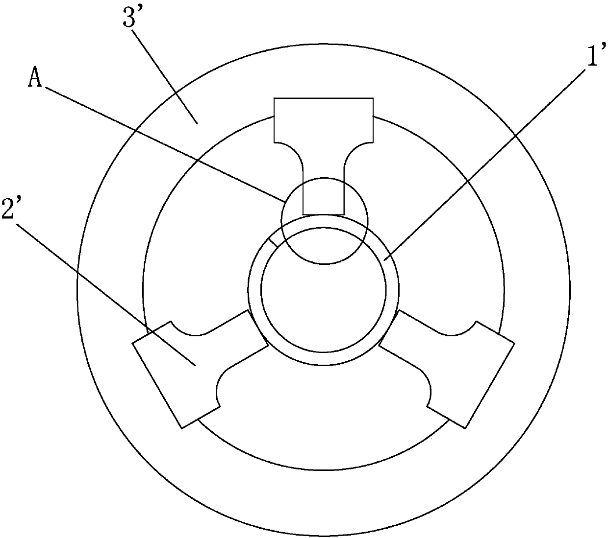
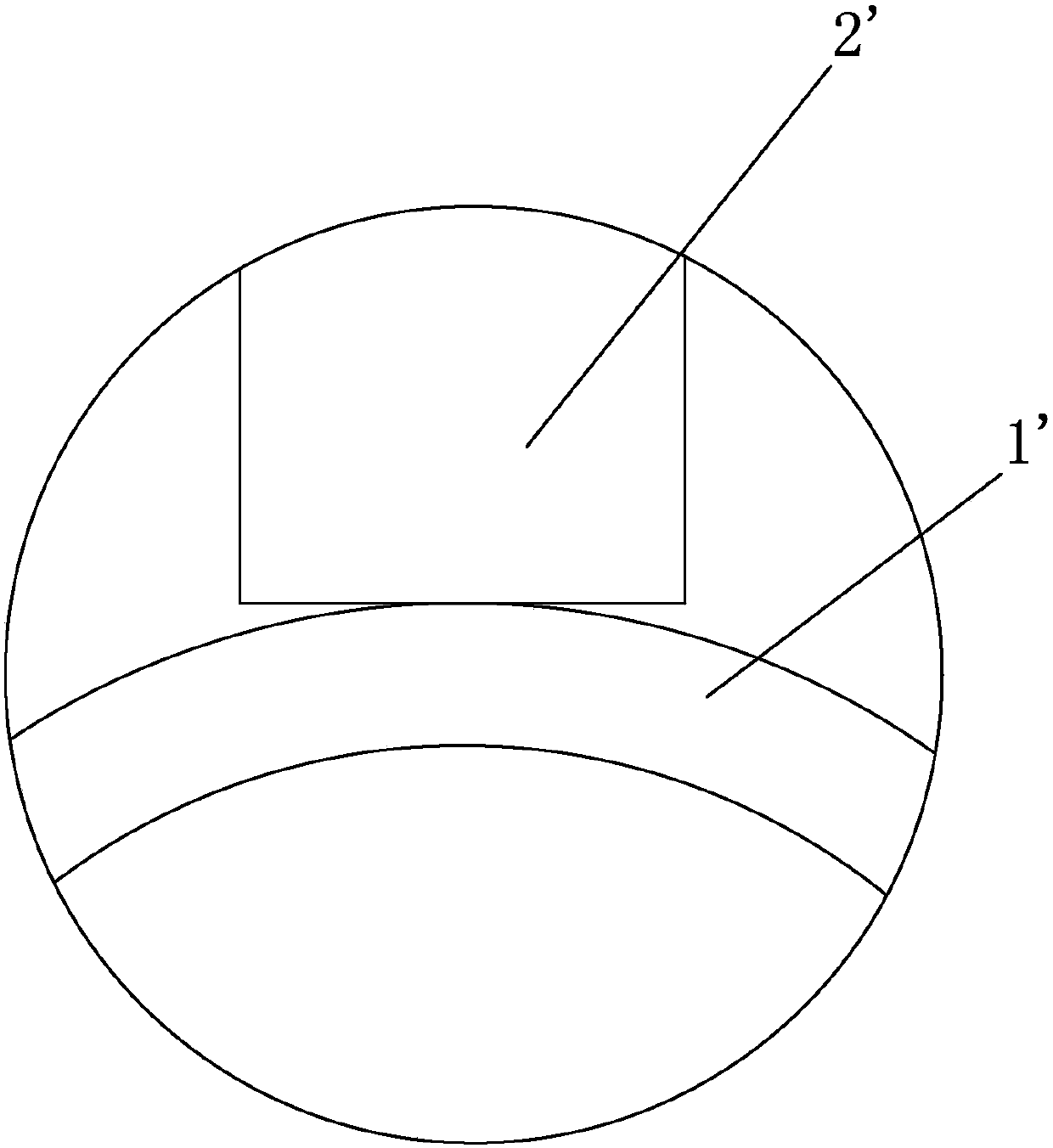
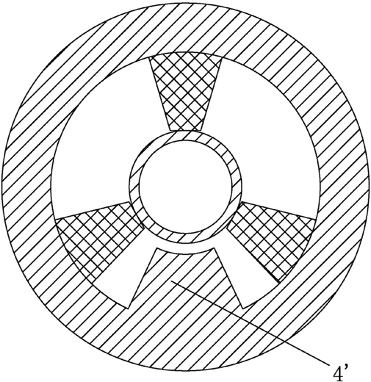
[0050] Such as Figures 4 to 11 As shown, an angular asymmetric helical slow wave structure, the slow wave structure includes a helix 1, a clamping rod 2 and a shell 3, the outer wall of the clamping rod 1 and the inner wall of the shell 3 connection and fixation; a metal loading 4 is arranged between the inner side wall of part of the clamping rod 2 in the clamping rod 2 and the helix 1; The helix 1 is connected and fixed.

[0051] In this embodiment, only a metal loading 4 is provided between a single clamping rod 2 and the helix 1; The first metallized coating layer, the metal loading 4 is connected and fixed to the first metallized coating layer, the metal loading 4 is connected and fixed to the wall surface of the corresponding helix 1 after exposure and photolithography, and the clamping rod The inner side wall of the remaining pa...


PUM


Abstract

The invention discloses an angular asymmetrical helical slow-wave structure comprising a helical line, clamping rods and a tube shell, wherein the outside walls of the clamping rods are connected and fixed with the inside wall of the tube shell; part of the inside wall of each clamping rod is connected and fixed with the helical line via a metal load; and the other part of the inside wall of each clamping rod is connected and fixed with the helical line. According to the angular asymmetrical helical slow-wave structure, the metal loads are arranged between the helical line and the graphic metallized clamping rods, so that the slow-wave structure has a characteristic of being angular asymmetrical due to the metal loads, while backward wave oscillation is restrained by a pai mode cut-off frequency band of a helical line dispersion curve, large-area effective contact is achieved between the helical line and the graphic metallized clamping rods, and contact thermal resistance between the helical line and the graphic metallized clamping rods is greatly reduced.

Description

technical field [0001] The invention relates to the field of vacuum electronic devices, in particular to an angular asymmetric helical slow-wave structure and a manufacturing method of the slow-wave structure Background technique [0002] Traveling wave tube is a kind of electronic device widely used in national defense and national economy, with good power, frequency band and gain performance. As the core components of distributed interaction devices such as traveling wave tubes and return wave oscillators, slow wave structures can reduce the phase velocity of electromagnetic waves and enable effective interaction between electrons and electromagnetic waves. Therefore, the shape and size of the slow-wave structure determine the distribution phase propagation velocity of the high-frequency field, thereby determining the interaction effect between the electron beam and the wave, and has a decisive impact on the performance of the traveling wave tube. [0003] The helix is ​​...

Claims


Application Information

Patent Timeline
Patent Type & Authority Patents(China)
IPC IPC(8): H01J23/26H01J25/34
CPCH01J23/26H01J25/34
Inventor 蔡军邬显平李莉莉冯进军杜英华潘攀
Owner NO 12 RES INST OF CETC
Why Eureka
Try Eureka