
Asymmetric Metal Loaded Helical Slow Wave Structure

A slow-wave structure and metal-loaded technology, which is applied to the circuit components of the time-of-flight electron tube, can solve problems such as return wave oscillation, improve performance stability, avoid electron injection and return wave interaction, and simplify assembly processes Effect

Active Publication Date: 2017-12-26
NO 12 RES INST OF CETC
View PDF5 Cites 0 Cited by
  • Summary
  • Abstract
  • Description
  • Claims
  • Application Information

AI Technical Summary

Problems solved by technology

[0005] The object of the present invention is to provide a helical slow wave structure in order to solve the problem of back wave oscillation existing in the existing traveling wave tube slow wave structure

Method used


Image

  • Asymmetric Metal Loaded Helical Slow Wave Structure
  • Asymmetric Metal Loaded Helical Slow Wave Structure
  • Asymmetric Metal Loaded Helical Slow Wave Structure

Examples


Embodiment Construction

[0032] In order to illustrate the present invention more clearly, the present invention will be further described below in conjunction with preferred embodiments and accompanying drawings. Similar parts in the figures are denoted by the same reference numerals. Those skilled in the art should understand that the content specifically described below is illustrative rather than restrictive, and should not limit the protection scope of the present invention.

[0033] Due to the introduction of angular asymmetric metal loading, adjusting the distance between the metal loading block and the helix and the width of the loading block can effectively change the width of the forbidden band, thereby affecting the effect of suppressing the return wave oscillation. This distance shall be between the minimum distance that can ensure that no mechanical contact between the metal loading block and the helix occurs under any mechanical or thermal stress and 35% of the outer radius of the helix....


PUM


Abstract

The invention relates to a helical line slow-wave structure with asymmetrical metal loaded blocks. The slow-wave structure comprises a tube shell, a helical line and a clamping rod positioned between the helical line and the tube shell, wherein the slow-wave structure further comprises at least one metal loaded block with asymmetrical angular directions; and the metal loaded blocks are positioned on the inner wall of the tube shell and are not in contact with the helical line. According to the helical line slow-wave structure provided by the invention, the metal load blocks with asymmetrical angular directions are arranged in the helical line slow-wave structure of any clamping structures, an electromagnetic wave transmission forbidden band is formed; therefore, interaction of electron beams and backward waves is avoided, so that the backward wave oscillation is restrained; and the helical line slow-wave structure can be manufactured conveniently under a normal line-cutting tube shell manufacturing process condition.

Description

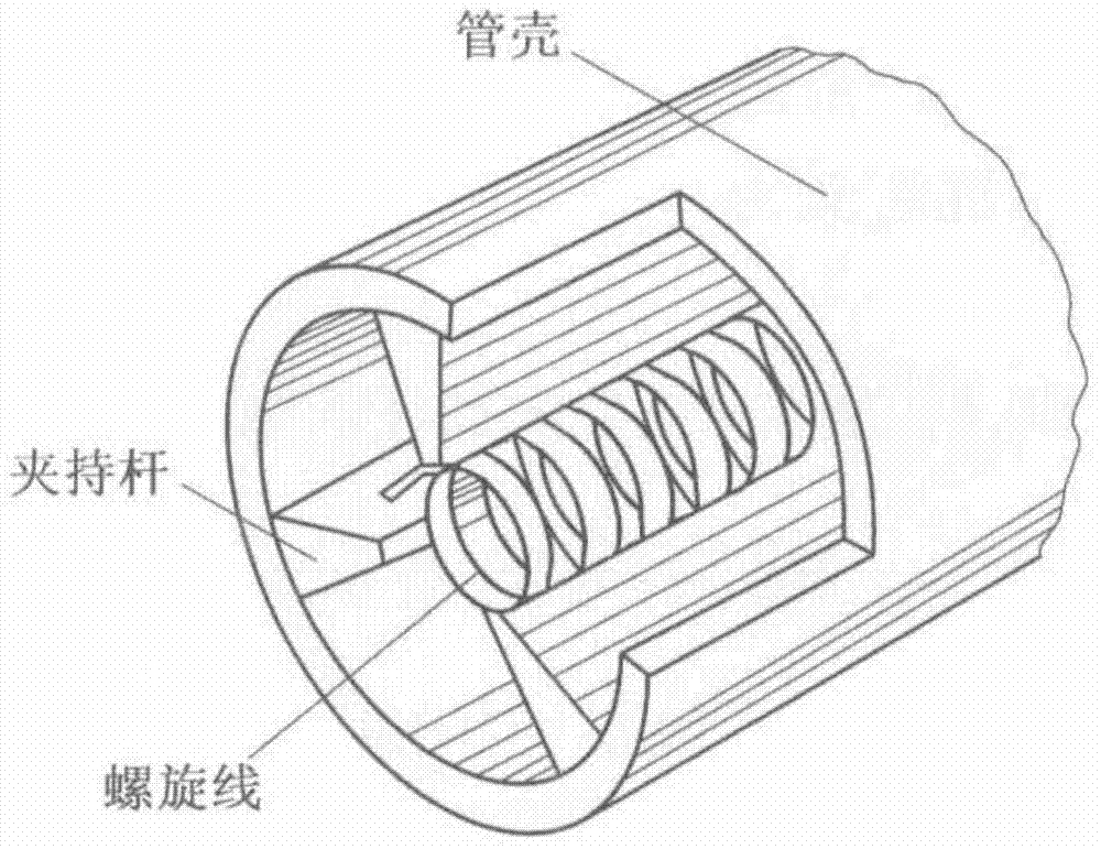
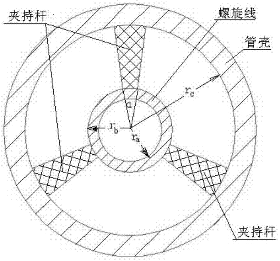
technical field [0001] The invention belongs to the field of microwave vacuum electronic devices, in particular to an angular asymmetric metal-loaded helical slow-wave structure. Background technique [0002] Helical slow wave structures are widely used in traveling wave tubes for satellite communications, electronic countermeasures and radars that require broadband operation. figure 1 Shown is a common helical slow wave structure, which is the core part of a broadband traveling wave tube. figure 2 yes figure 1 The cross-sectional view of the helical slow wave structure shown, the structure includes a shell, a helix arranged coaxially with the shell, and three clamping rods arranged symmetrically between the helix and the shell. The clamping rod can have various shapes, and it can also be a variety of shapes such as rectangle, circle and character shape except the wedge shape shown in the figure. figure 2 middle r a is the inner radius of the spiral, r b is the outer ...

Claims


Application Information

Patent Timeline
Patent Type & Authority Patents(China)
IPC IPC(8): H01J23/26
CPCH01J23/26
Inventor 邬显平蔡军冯进军陈波
Owner NO 12 RES INST OF CETC
Learn More