Distributed radiation coupling loss circuit applied to gyrotron traveling wave tube

A technology of radiation coupling and loss circuit, which is applied to the coupling device, circuit, and cooling method of transit time type electron tubes, etc. To achieve the best, affect the injection-wave interaction efficiency and output power of the gyroscopic traveling wave tube, and achieve the effect of improving the injection-wave interaction efficiency and output energy

Active Publication Date: 2022-05-17
UNIV OF ELECTRONICS SCI & TECH OF CHINA
View PDF14 Cites 2 Cited by
  • Summary
  • Abstract
  • Description
  • Claims
  • Application Information

AI Technical Summary

Problems solved by technology

In traditional medium-loaded gyrotraveling wave tubes, electron beams interact with each other in the high-frequency structure to generate high-power electromagnetic field energy, which causes the lossy medium in the medium-loaded section to absorb excess energy to generate high temperature and overheat the outgassing, thereby affecting the gyrotron motion. Wave tube stability and power handling
At the same time, due to the large changes in the dispersion curve and field distribution of the working mode of the electromagnetic wave during the medium loading, the dispersion curve of the electron beam and the high-frequency electromagnetic field cannot achieve the best synchronization conditions during the beam-wave interaction process. good, which affects the injection-wave interaction efficiency and output power of the gyro TWT

Method used


Image

  • Distributed radiation coupling loss circuit applied to gyrotron traveling wave tube
  • Distributed radiation coupling loss circuit applied to gyrotron traveling wave tube
  • Distributed radiation coupling loss circuit applied to gyrotron traveling wave tube

Examples


Embodiment Construction

[0022] The present invention will be further described in detail below in conjunction with a design example of a high-frequency interaction circuit of a cyclotron TWT with a Ku-band distributed radiation coupling loss circuit structure and the accompanying drawings.

[0023] The technical index requirements of the high-frequency interaction circuit of the cyclotron TWT with the Ku-band distributed radiation coupling loss circuit structure:

[0024] Main waveguide working mode: TE 11 mold;

[0025] Working frequency band: Ku band (14.5GHz-18GHz), working voltage 60kV, working current 10A.

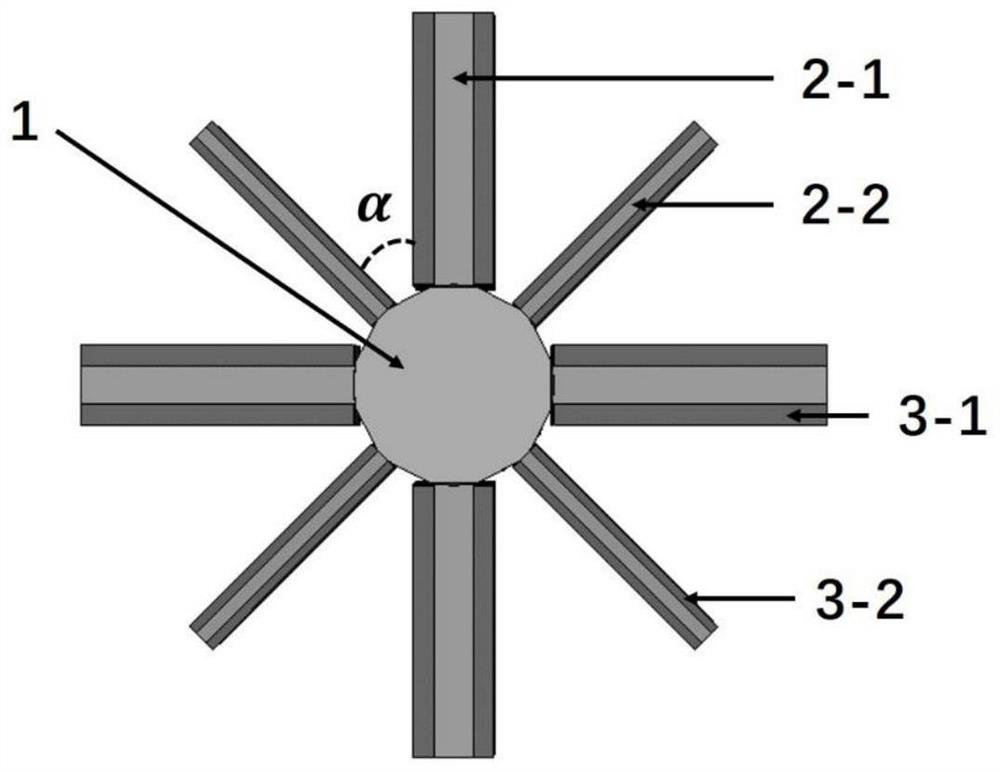
[0026] This example proposes a distributed radiation coupling loss circuit applied to a gyrotraveling wave tube. Its structure is as attached figure 2 , 3 , 4, as shown in appendix 3, including the standard smooth circular waveguide 1, two types of 8 diamond-shaped waveguides 2-1 and 2-2 with uniform angular distribution on the outer wall of the circular waveguide, and the two broad side...


PUM


Abstract

The invention discloses a distributed radiation coupling loss circuit applied to a gyrotron traveling wave tube, and belongs to the technical field of microwave and millimeter wave vacuum devices. According to the invention, self-oscillation of a TE11 mode and backward wave oscillation of a TE21 mode can be effectively suppressed. Meanwhile, high-power electromagnetic energy generated due to beam-wave interaction is guided into the rhombic waveguide and can be absorbed by the attenuation materials tightly attached to the side walls of the two wide edges of the rectangular waveguide. The surface area of the continuous attenuation material tightly attached to the side walls of the two wide edges of the rectangular waveguide is far larger than that of an attenuation ceramic ring in a high-frequency interaction circuit of a traditional medium-loaded gyrotron traveling wave tube, so that the heat dissipation area is increased; the problem that the medium loading section of the traditional medium loading gyrotron traveling wave tube absorbs excessive energy to generate high temperature and then overheat and exhaust gas is solved. Therefore, the beam-wave interaction efficiency, the stability and the power capacity of the gyrotron traveling wave tube are effectively improved.

Description

technical field [0001] The invention belongs to the technical field of microwave and millimeter wave vacuum devices, in particular to a distributed radiation coupling loss circuit applied to a cyclotron traveling wave tube. Background technique [0002] The gyrotron traveling wave tube has the characteristics of high efficiency, high power, wide frequency band, and high gain, so it has broad application prospects in the fields of high-resolution radar, high-power communication systems, and electronic warfare systems, and has received domestic and international attention. highly valued. [0003] The high-frequency interaction circuit of the medium-loaded TWT is the core of the TWT, and its structure affects the bandwidth, gain, and efficiency of the TWT. The high-frequency interaction circuit of the traditional medium-loaded Gyro TWT generally adopts a two-stage structure: a smooth waveguide section and a dielectric-loaded section. In traditional medium-loaded gyrotraveling...

Claims


Application Information

Patent Timeline
Patent Type & Authority Applications(China)
IPC IPC(8): H01J23/54H01J23/00
CPCH01J23/54H01J23/005
Inventor 刘国全西原曹英键蒋伟王建勋罗勇
Owner UNIV OF ELECTRONICS SCI & TECH OF CHINA
Why Eureka
Try Eureka