Method, equipment and system for precise time synchronization

A technology for precise time synchronization and network equipment. It is applied in time division multiplexing systems, electrical components, and multiplexing communications. It can solve problems such as hardware implementation difficulties and multi-hardware judgment logic. The effect of time synchronization

Inactive Publication Date: 2010-12-01
GLOBAL INNOVATION AGGREGATORS LLC
View PDF3 Cites 12 Cited by
  • Summary
  • Abstract
  • Description
  • Claims
  • Application Information

AI Technical Summary

Problems solved by technology

[0007] The inventor finds in the process of realizing the present invention, PTP port search PTP message needs to compare encapsulation information layer by layer according to the layer network structure, when the layer network layer number is more, need more hardware judgment logic, and, after modifying the PTP message, It may be necessary to re-calculate the verification data for the encapsulation of the involved multi-layer network, which has high requirements on the processing speed and logic scale of the hardware, and it is difficult to realize the hardware

Method used


Image

  • Method, equipment and system for precise time synchronization
  • Method, equipment and system for precise time synchronization
  • Method, equipment and system for precise time synchronization

Examples


Embodiment 1

[0034] An embodiment of the present invention provides a precise time synchronization method, which will be described in detail below with reference to the accompanying drawings.

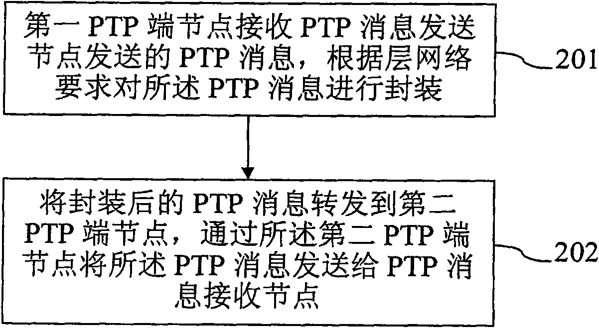
[0035] figure 2 For the method flowchart of the embodiment of the present invention, please refer to figure 2 , the embodiment of the present invention is based on a layered network structure, and the method mainly includes:

[0036] 201: The first PTP end node receives the PTP message sent by the PTP message sending node, and encapsulates the PTP message according to the requirements of the layer network;

[0037] 202: Forward the encapsulated PTP message to a second PTP end node, send the PTP message to the PTP message receiving node through the second PTP end node, and perform the process according to the received PTP message through the PTP message receiving node Precise time synchronization.

[0038] The method in the embodiment of the present invention is applied to a system with a layere...

Embodiment 2

[0050] An embodiment of the present invention also provides a method for precise time synchronization based on a layered network structure, which will be described below with reference to the accompanying drawings.

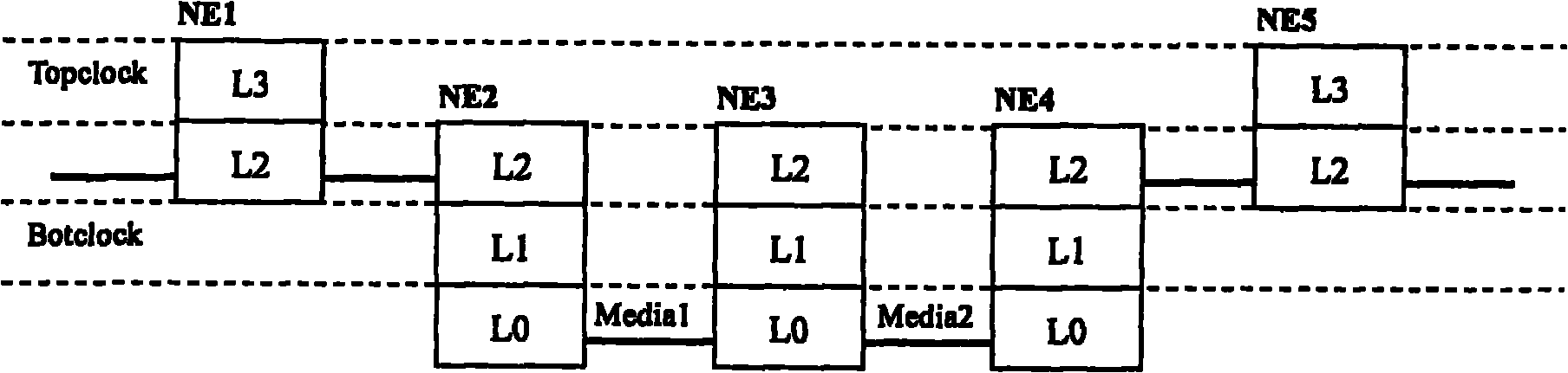
[0051] Figure 4 is based on image 3 The information interaction flow chart of each node device of the data communication network made by the schematic diagram shown, please refer to Figure 4 , in this embodiment, NE1 is the PTP message sending node of the Topclock layer network; NE2 and NE4 are the PTP end nodes of the Botclock layer network; NE5 is the PTP message receiving node of the Topclock layer network; NE3 is optional and is the Botclock layer network P2P clock node. Such as Figure 4 As shown, the method of the present embodiment mainly includes:

[0052] 401: The PTP message sending node NE1 of the Topclock layer network sends the PTP general message or PTP event message of the Topclock layer network to the PTP end node NE2 of the Botclock layer n...

Embodiment 3

[0071] An embodiment of the present invention also provides a method for precise time synchronization based on a layered network structure, which will be described below with reference to the accompanying drawings.

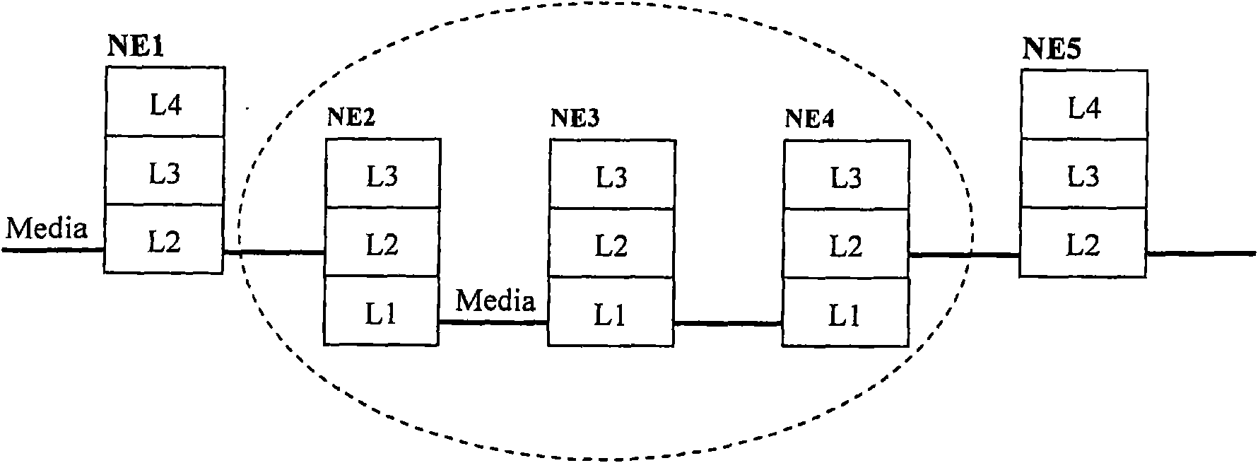
[0072] Figure 5 This embodiment divides the schematic diagram of the PTP processing layer according to the network structure of the service layer, please refer to Figure 5 , in this embodiment, the data communication network includes five PTP nodes ND1, ND2, ND3, ND4, and ND5, forming five layer networks NDL1-NDL5. ND1, ND5 support NDL3-NDL5 layer network functions, ND2, ND3, ND4 support NDL1-NDL4 layer network functions.

[0073] In this embodiment, the NDL5 layer network is selected to run PTP, which is marked as a Topclock layer network, and ND1 and ND5 are adjacent PTP nodes of the Topclock layer network. ND1 is the master clock and ND5 is the slave clock. Within the scope of ND2, ND3, and ND4, NDL2 is the lowest layer network that can perform end-to-end ...


PUM


Abstract

The embodiment of the invention provides a method, equipment and a system for layer network structure-based precise time synchronization. The method comprises the following steps of: receiving a PTP message sent by a PTP message sending node by a first precise time protocol (PTP) end node, and encapsulating the PTP message according to the requirement of a layer network; and forwarding the encapsulated PTP message to a second PTP end node, sending the PTP message to a PTP message receiving node through the second PTP end node, and performing the precise time synchronization through the PTP message receiving node. Through the method, the equipment and the system of the embodiment of the invention, the PTP message is subjected to layering according to a layer network structure, so that the load of processing the PTP message by a PTP port is relieved, and the layer network structure is favorable for realizing the precise time synchronization.

Description

technical field [0001] The present invention relates to precise time synchronization, in particular to a precise time synchronization method, device and system. Background technique [0002] Precise time synchronization is widely used in some 2G / 3G (2nd Generation, second generation / 3rd Generation, third generation) mobile communication networks, automated industrial manufacturing, and delay testing and measurement. The transmission mainly relies on GPS (Global Positioning System, Global Positioning System) equipment or a local bus. The rapid development of data communication networks is gradually deepening the above application fields. How to achieve precise time synchronization based on data networks has become a key issue in the current communication field. [0003] At present, the layered network structure is one of the main application methods of the current data communication network. Layer networks operate independently of each other. Every time data information ent...

Claims


Application Information

Patent Timeline
Patent Type & Authority Applications(China)
IPC IPC(8): H04J3/06
Inventor 杨祖发李明春
Owner GLOBAL INNOVATION AGGREGATORS LLC
Why Eureka
Try Eureka