Optical line terminal, optical add-drop multiplexer and optical access system

A technology of optical add-drop multiplexer and optical line terminal, which is applied in the field of optical access, can solve problems such as network paralysis, and achieve the effect of backup protection

Active Publication Date: 2010-12-01
HUAWEI TECH CO LTD
View PDF6 Cites 14 Cited by
  • Summary
  • Abstract
  • Description
  • Claims
  • Application Information

AI Technical Summary

Problems solved by technology

[0005] The inventor finds that the prior art has the following problems in the process of realizing the present invention: in HPON, there are very many optical network terminals (ONTs) carried by a network node (NN), if there is a break in the backbone optical fiber of the WDM ring, it will cause massive network crash

Method used


Image

  • Optical line terminal, optical add-drop multiplexer and optical access system
  • Optical line terminal, optical add-drop multiplexer and optical access system
  • Optical line terminal, optical add-drop multiplexer and optical access system

Examples


Embodiment 1

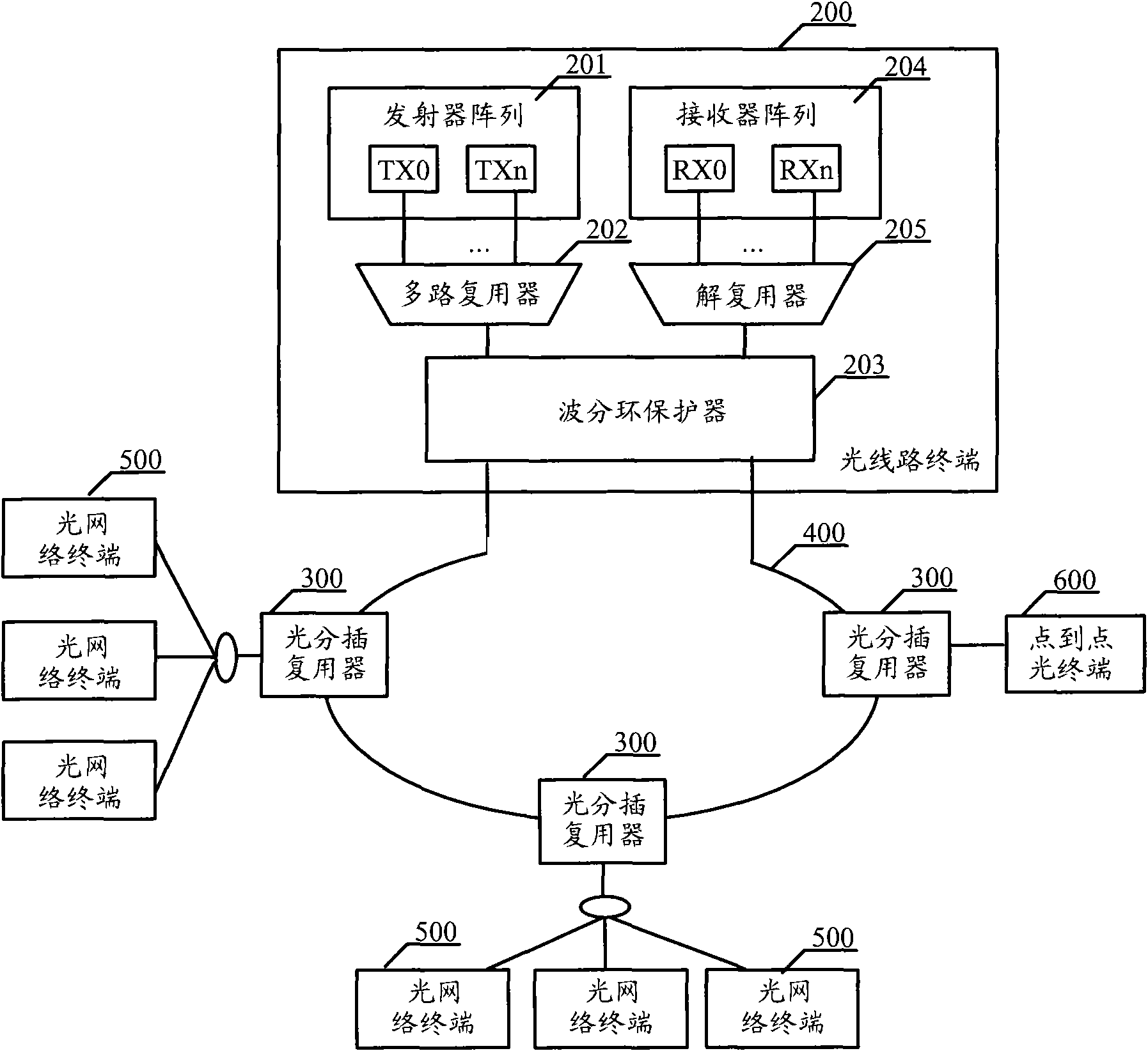
[0045] Embodiment one, such as figure 2 As shown, the embodiment of the present invention provides an optical line terminal 200, including:

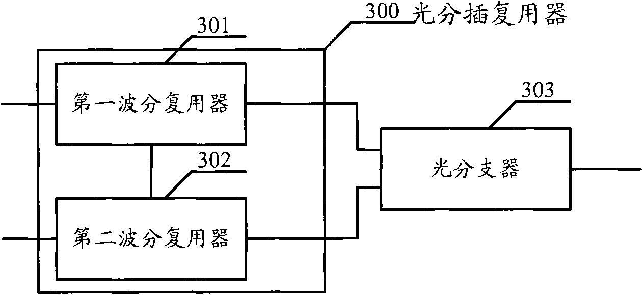
[0046] Transmitter array 201, multiplexer 202, WDM ring protector 203, receiver array 204, demultiplexer 205; in addition figure 2 It is a diagram of the system where the optical line terminal 200 is located, and also includes: an optical add-drop multiplexer 300 connected to the optical line terminal 200 through a wavelength division multiplexing ring 400, an optical network terminal 500 or a point-to-point optical terminal 600 and an optical add-drop multiplexer The device 300 is connected as the receiving end of the downlink optical signal and the sending end of the uplink optical signal.

[0047] In the downlink direction of the optical signal, the propagation path of the optical signal is:

[0048] A transmitter array 201, configured to transmit downlink optical signals;

[0049] The multiplexer 202 is configured to multiplex the...

Embodiment 2

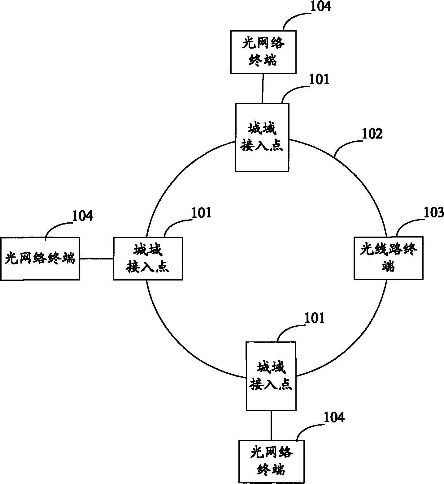
[0068] Embodiment 2, for the optical access system provided in this embodiment, in the embodiment of the present invention, the position of each device in the system does not need to be changed, and the position of each device in the system can be referred to figure 1 The positions of the devices in the system will not be described one by one in the subsequent embodiments. Such as Figure 4 Shown is a schematic diagram of a WDM+TDM hybrid PON system with backup protection. The whole system includes an optical line terminal 1101 (Optical Line Terminal, OLT) located in a central office (Central Office, CO), an outdoor optical add-drop multiplexer 1111 (Optical Add-Drop Multiplexer, OADM), and a WDM ring 1112 . Wherein, the optical line terminal 1101 includes: a transmitter (Transmitter, TX) array 1102, a receiver (Receiver, RX) array 1103, a multiplexer 1104 (multiplexer, MUX) / demultiplexer 1105 (De-multiplexer, DEMUX ), 2:2 splitter 1106, 2:2 splitter 1107, optical switch 110...

Embodiment 3

[0086] Embodiment 3, the optical access system provided by this embodiment, such as Figure 8 with Figure 9 As shown, it is a schematic diagram of a WDM+TDM hybrid PON system with backup protection. The difference from Embodiment 2 is that the transmitter and receiver (Receiver, RX) in the transmitter (Transmitter, TX) array 1502 in this embodiment ) The receivers in the array 1503 have one-to-one correspondence. In a pair of receivers and transmitters, the wavelength of the optical signal received by the receiver is different from the wavelength of the optical signal sent by the transmitter. In the second embodiment, the optical signal received by the receiver The wavelength is the same as the wavelength of the optical signal sent by the transmitter,

[0087] The entire optical access system includes an optical line terminal 1501 (Optical Line Terminal, OLT) located in a central office (Central Office, CO), an outdoor optical add-drop multiplexer 1511 (Optical Add-Drop Mult...


PUM


Abstract

The embodiment of the invention discloses an optical access system comprising one or more optical add-drop multiplexers sequentially connected through optical fibers in series to form a wavelength division multiplexing ring, wherein both ends of the wavelength division multiplexing ring are connected with one optical line terminal. The optical line terminal comprises a transmitter array, a multiplexer, a wavelength division ring protector, a receiver array and a demultiplexer, wherein the wavelength division ring protector is used for detecting whether the wavelength division multiplexing ring is broken or not; when the wavelength division multiplexing ring is normal, multiplexed downstream optical signals are transmitted to the wavelength division multiplexing ring from one end; when the wavelength division multiplexing ring is broken, the downstream optical signals are transmitted to the wavelength division multiplexing ring from both ends; and when the wavelength division multiplexing ring is normal, upstream optical signals are received from one end of the wavelength division multiplexing ring, and when the wavelength division multiplexing ring is broken, the upstream optical signals are received from both ends of the wavelength division multiplexing ring, and then the received upstream optical signals are transmitted to the demultiplexer.

Description

technical field [0001] The invention relates to the field of optical access, in particular to an optical line terminal, an optical add / drop multiplexer and an optical access system. Background technique [0002] In the field of optical access, there are currently two mainstream technical directions, one is time division multiplexed passive optical network (Time Division Multiplexed Passive Optical Network, TDM-PON), the other is wavelength division multiplexed passive optical network (Wavelength Division Multiplexed Passive Optical Network, WDM-PON); TDM-PON and WDM-PON have their own advantages, and TDM-PON has: good statistical multiplexing gain, high peak rate, low cost, single-copy broadcast, etc. ; WDM-PON has the advantages of huge bandwidth, small link loss, good security and robustness, and high sensitivity of continuous reception. [0003] With the increase of user bandwidth requirements and the continuous emergence of various emerging services, large user capacity...

Claims


Application Information

Patent Timeline
Patent Type & Authority Applications(China)
IPC IPC(8): H04Q11/00H04J14/02
Inventor 林华枫欧阳伟龙
Owner HUAWEI TECH CO LTD
Why Eureka
Try Eureka