
Two-roll wire rolling mill

A rolling mill and wire rod technology, applied in metal rolling and other directions, can solve the problems of high energy consumption, difficult threading, easy loss of molds, etc., achieve uniform arrangement, good material density, and reduce useless power

Inactive Publication Date: 2010-12-08
常德市恒德机械制造有限公司
View PDF0 Cites 10 Cited by
  • Summary
  • Abstract
  • Description
  • Claims
  • Application Information

AI Technical Summary

Problems solved by technology

[0003] In order to overcome the disadvantages of high energy consumption, difficult threading and easy wear and tear of the traditional water tank type wire drawing machine, the present invention proposes a new product of a two-roller wire rod rolling machine

Method used


Image

  • Two-roll wire rolling mill
  • Two-roll wire rolling mill
  • Two-roll wire rolling mill

Examples


Embodiment Construction

[0031] Below in conjunction with accompanying drawing the specific embodiment of the present invention is described in detail as follows:

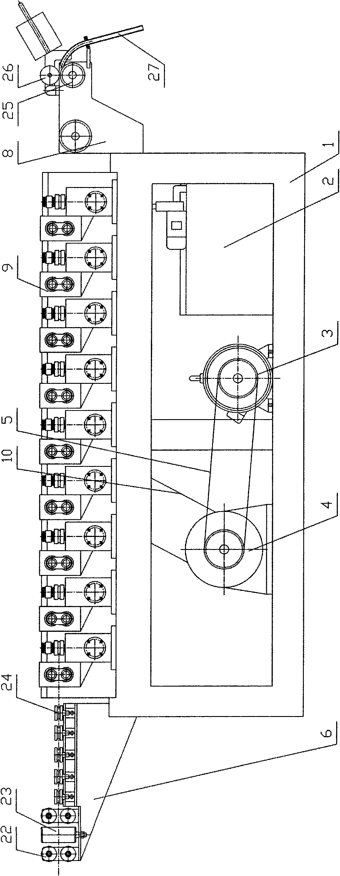
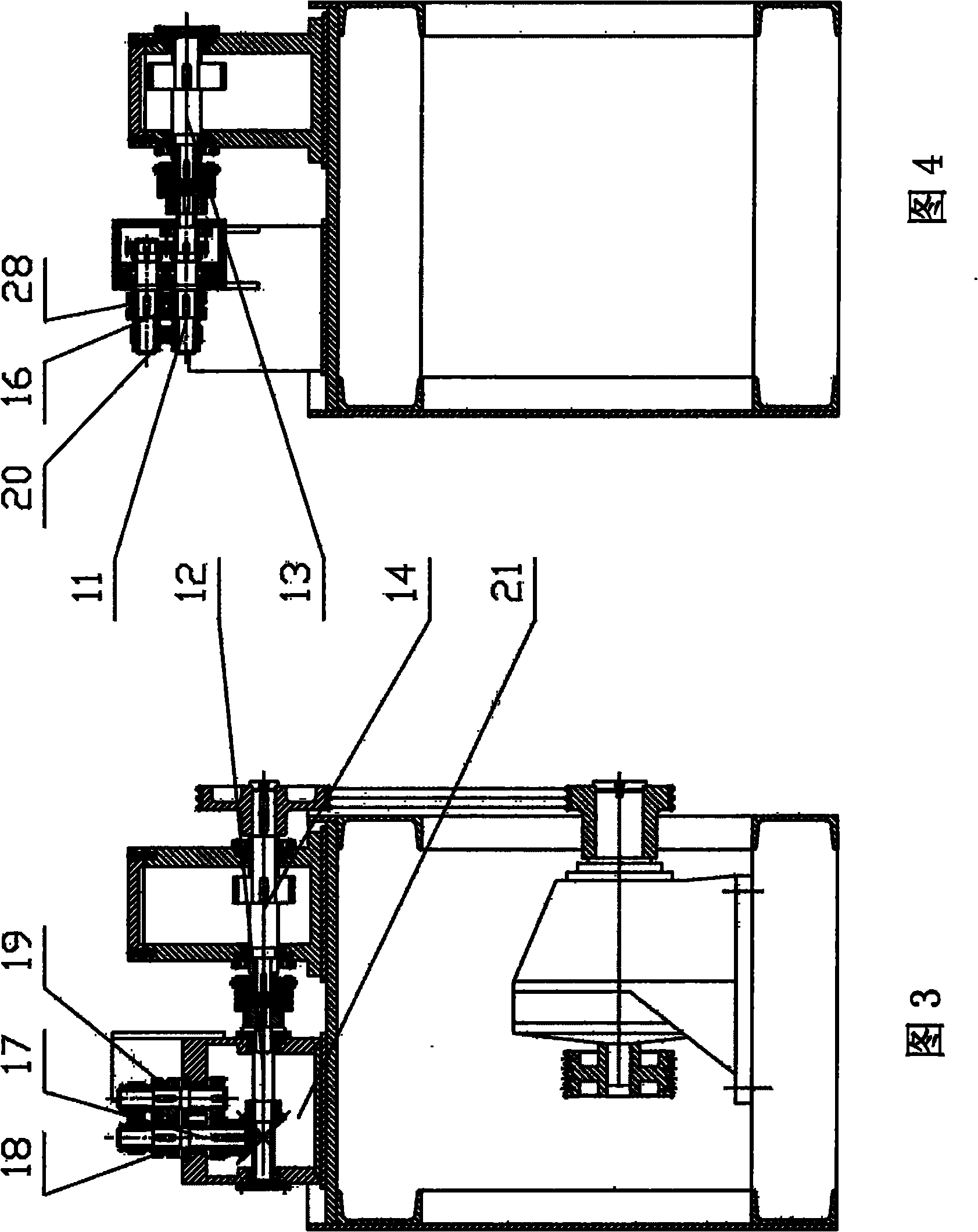
[0032] exist figure 1 , 2 Among them, the two-roller wire rolling mill of the present invention includes a frame 1, a lubrication system 2 and an electric control part, and the lower part of the frame 1 is equipped with a motor 3 and a speed reducer 4, between the output shaft of the motor 3 and the input shaft of the speed reducer 4 Connected with a belt 5, on the frame 1, an incoming line straightening mechanism 6, a main transmission box 7 and an outgoing line drop barrel mechanism 8 are arranged in sequence, and 9 small boxes 9 are installed on one side of the main transmission box 7, each small box The body 9 is equipped with a pair of vertical rolls and a pair of horizontal rolls, the output shaft of the reducer 4 and the input shaft of the main transmission box 7 are connected by a chain 10, and the upper and lower two-layer transm...


PUM


Abstract

The invention discloses a two-roll wire rolling mill which comprises a stand, a lubricating system and an electric control part, wherein a power machine and a reducer are installed at the lower part of the stand, the output shaft of the power machine is connected with the input shaft of the reducer through a transmission device, an inlet wire straightening mechanism, a main transmission box and an outlet wire barrel falling mechanism are sequentially installed at the upper part of the stand, a plurality of small box bodies are installed at one side of the main transmission box, and a pair of vertical rolls and a pair of horizontal rolls are installed on each small box body. Compared with the traditional wire drawing machine, the two-roll wire rolling mill has the advantages of compact structure, smooth transmission, low noise, low energy consumption, high yield, convenient threading operation, difficult wire breakage in the postorder drawing process and the like.

Description

technical field [0001] The invention relates to non-ferrous metal processing, namely a two-roller wire rod rolling mill. Background technique [0002] The traditional water tank type wire drawing machine is composed of a motor, a transmission box, a tower wheel, a mold base and a wire take-up mechanism. Its main working principle is to pass the wire (according to a certain amount of compression) through the mold fixed on the mold base, and then The wire is wound on the tower pulley, and the power transmitted by the motor is used to stretch and thin the wire to obtain wire specifications of different diameters. When using a traditional water tank wire drawing machine to obtain wire, there is sliding friction between the wire and the die. Therefore, in the wire drawing process, the wear of the die is very fast. When the die wears out, its own compression ratio changes from the original design mechanical compression ratio, and due to the corresponding sliding friction between ...

Claims


Application Information

Patent Timeline
Patent Type & Authority Applications(China)
IPC IPC(8): B21B1/16
Inventor 孙上林王刚祝云阶
Owner 常德市恒德机械制造有限公司
Learn More