Roller-lifting proportional and synchronous hydraulic control system

A technology of hydraulic control system and lifting hydraulic cylinder, which is applied in the direction of rolling mill control devices, metal rolling, manufacturing tools, etc., can solve the problems of inconvenient displacement control, etc., and achieve convenient and fast adjustment, high precision displacement control, and high synchronization precision Effect

Inactive Publication Date: 2010-12-08
TAIYUAN HEAVY IND
View PDF3 Cites 18 Cited by
  • Summary
  • Abstract
  • Description
  • Claims
  • Application Information

AI Technical Summary

Problems solved by technology

[0005] The purpose of the present invention is to overcome the shortcomings of the existing hydraulic control technology, provide a proportional synchronous hydraulic control system for roller table lifting, and solve the problem that the current hydraulic control system cannot conveniently perform displacement control

Method used


Image

  • Roller-lifting proportional and synchronous hydraulic control system
  • Roller-lifting proportional and synchronous hydraulic control system
  • Roller-lifting proportional and synchronous hydraulic control system

Examples


Embodiment Construction

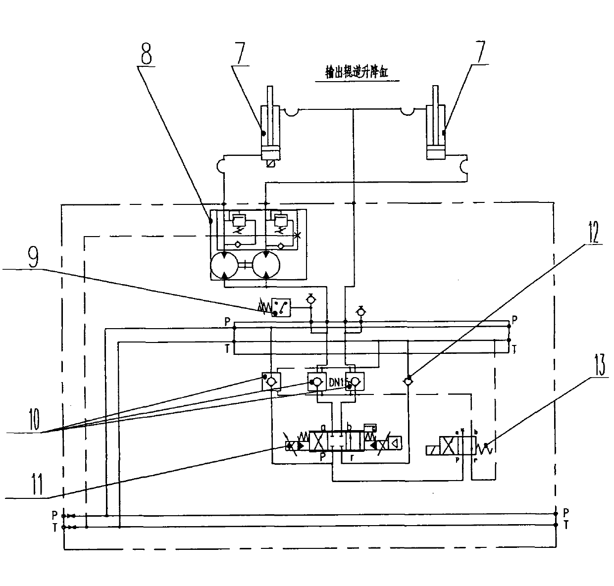
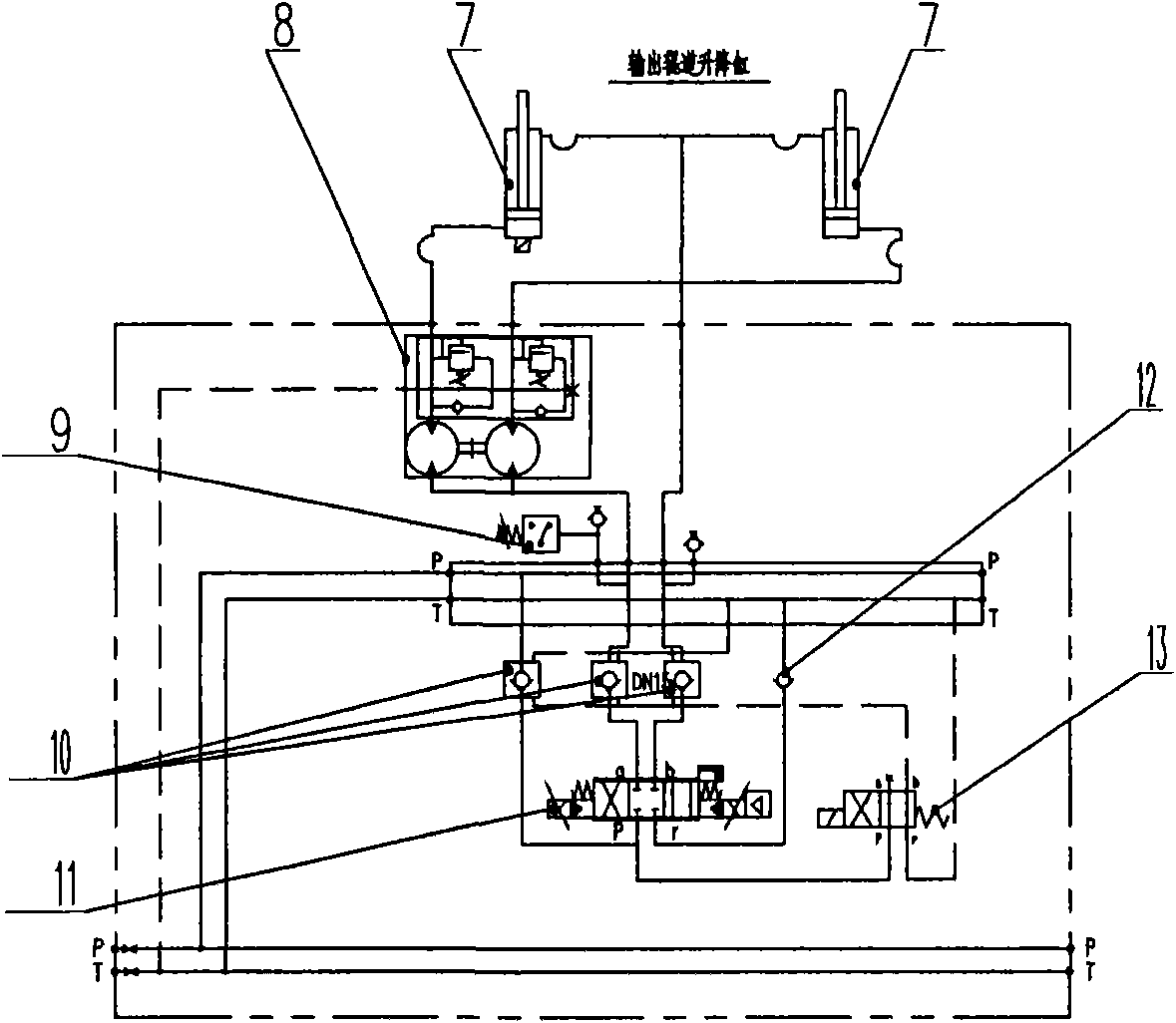
[0016] Such as figure 2 As shown, a proportional synchronous hydraulic control system for roller table lifting is composed of a proportional valve 11, a hydraulic control check valve 10, a reversing valve 13, a pressure relay 9, a synchronous motor 8, a check valve 12 and two rollers There are three hydraulically controlled one-way valves 10, which are respectively connected to the p port, a port and b port of the proportional valve 11, and the a port of the proportional valve 11 passes through the hydraulic control The check valve 10 is connected to the pressure relay 9 and the oil inlet of the synchronous motor 8, and the two oil outlets of the synchronous motor 8 are respectively connected to the piston chambers of the two roller lift hydraulic cylinders 7, The piston rod cavity of the roller table lifting hydraulic cylinder 7 is connected in parallel to the b port of the proportional valve 11 through the hydraulic control check valve 10, and the b port of the reversing va...


PUM


Abstract

The invention provides a roller-lifting proportional and synchronous hydraulic control system, relating to a perforating machine. The invention solves the problem that the traditional hydraulic control system can not control the displacement conveniently. The roller-lifting proportional and synchronous hydraulic control system comprises a proportional valve, hydraulic control one-way valves, a change valve, a pressure relay, a synchronous motor and two roller-lifting hydraulic cylinders, wherein the three hydraulic control one-way valves are respectively connected with a port p, a port a and a port b of the proportional valve, and the port a of the proportional valve is connected with the pressure relay and an oil inlet of the synchronous motor through the hydraulic control one-way valves; two oil outlets of the synchronous motor are respectively connected with piston cavities of the two roller-lifting hydraulic cylinders, and piston rod cavities of the roller-lifting hydraulic cylinders are connected in parallel and then connected with the port b of the proportional valve through the hydraulic control one-way valves; and a port b of the change valve is connected with oil control ports of the hydraulic control one-way valves, an oil return port of the change valve is connected with return oil of the system, and oil drain ports of the hydraulic control one-way valves are connected with oil return pipes of the system. The roller-lifting proportional and synchronous hydraulic control system can be used for controlling the synchronous movement of a plurality of hydraulic cylinders by using one proportional valve.

Description

technical field [0001] The invention relates to a hydraulic control system in which a proportional valve controls multiple hydraulic cylinders, has the function of controlling the displacement and synchronous action of the multiple hydraulic cylinders, and specifically relates to a hydraulic control system for lifting and lowering a section of roller table at the exit table of a piercing machine. technical background [0002] The roller table section of the piercing machine exit table is an important production equipment of the piercing machine, which has the functions of transporting the capillary, supporting the ejector rod (mandrel), and supporting the capillary. [0003] The current hydraulic control system for the lifting of the roller table of the exit table of the piercing machine is as follows: figure 1 As shown: No. 1 roller table lifting cylinder 1 and No. 2 roller table lifting cylinder 2 are respectively controlled by two hydraulic circuits, and the two hydraulic...

Claims


Application Information

Patent Timeline
Patent Type & Authority Applications(China)
IPC IPC(8): B21B19/04B21B37/00F15B11/22
Inventor 曹美忠
Owner TAIYUAN HEAVY IND
Why Eureka
Try Eureka