Turnout execution unit of computer interlocking system and working method thereof

A technology of computer interlocking and execution unit, applied in the interlocking device between switch and signal, program control in sequence/logic controller, railway car body parts, etc. Long time and other problems, to achieve high reliability, reduce costs, and achieve the effect of electrical isolation

Active Publication Date: 2010-12-08
上海亨钧科技股份有限公司
View PDF8 Cites 17 Cited by
  • Summary
  • Abstract
  • Description
  • Claims
  • Application Information

AI Technical Summary

Problems solved by technology

[0004] The patent number is ZL 200920209810.2, and the publication date is June 23, 2010. The Chinese utility model patent discloses an interlocking turnout actuator circuit. The actuator circuit realizes fixed operation and anti-manipulation control, the circuit structure and Figures 1a to 1d The illustrated circuit structure is similar, only the first to fourth electronic switches are also relay switches to achieve interlock control on both software and hardware, if the first to fourth electronic switches are other types of switches, two controllers are required MCU1 and MCU2 perform software fault judgment. If the execution unit only judges faults through software and executes fault-to-safety guidance according to the judgment structure, the defect on the one hand is that the probability of fault-oriented safety failure increases, because MCU1 and /or when MCU2 breaks down, it is impossible to perform fa

Method used


Image

  • Turnout execution unit of computer interlocking system and working method thereof
  • Turnout execution unit of computer interlocking system and working method thereof
  • Turnout execution unit of computer interlocking system and working method thereof

Examples


Embodiment Construction

[0041] The specific implementation of the switch execution unit of the computer interlocking system of the present invention will now be described with reference to the accompanying drawings.

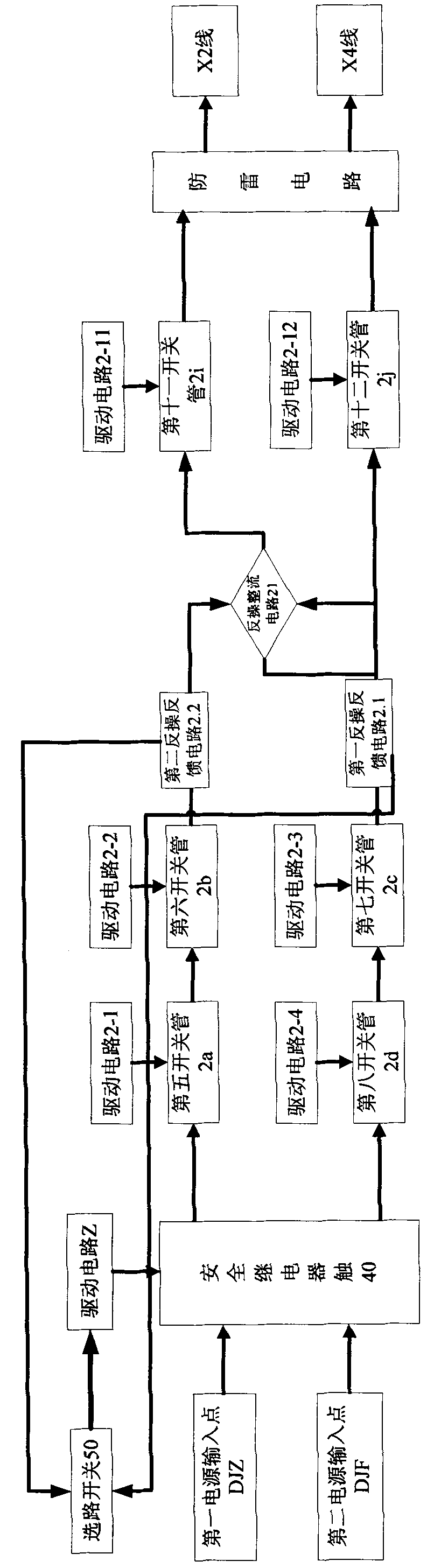
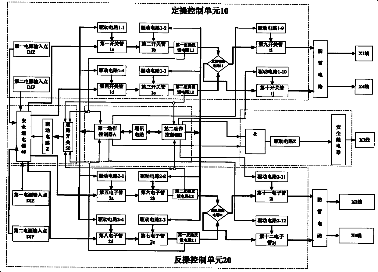
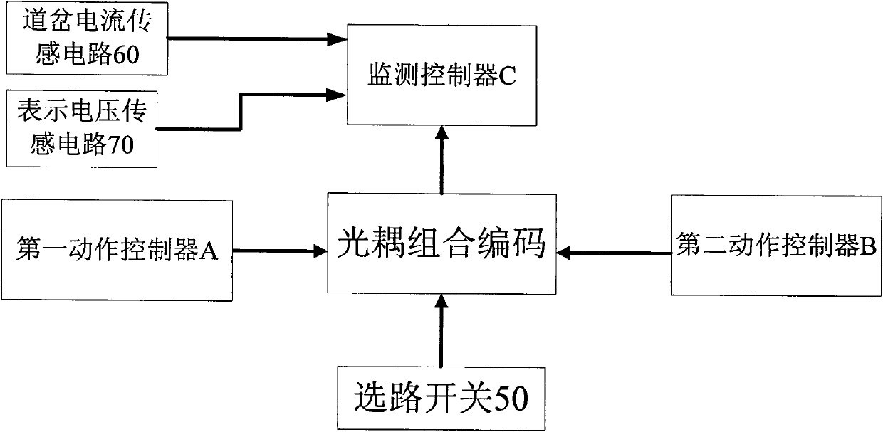
[0042] Such as figure 2 , 3 As shown in and 4, the switch execution unit of the computer interlocking system of the present invention includes a first action controller A and a second action controller B, and a fixed operation control circuit 10 and a reverse operation control circuit that are jointly controlled by the two 20. The switch execution unit further includes a safety relay 40 and a routing switch 50.

[0043] The fixed operation control circuit 10 includes first to fourth switch tubes 1a, 1b, 1c, and 1d. The first and second switch tubes 1a and 1b are electrically connected to the first power input point DJZ and used for switching The X1 line of the machine is electrically connected between the fixed operation output points, where the first and second switch tubes 1a and 1b are u...


PUM


Abstract

The invention discloses a turnout execution unit of a computer interlocking system and a working method thereof. The turnout execution unit comprises a first action controller, a second action controller and a directional-operation and reverse-operation control circuit controlled by the first action controller and the second action controller, and the turnout execution unit also comprises a safety relay and a select switch; the first action controller and the second action controller are used for controlling a group of switching tubes on the directional-operation and reverse-operation control circuit; the AC input directional-operation and the reverse-operation control circuit is controlled by a normally-opened switch of the safety relay; the select switch is in communicating connection with the first action controller, the second action controller and a signal acquisition unit; and the first action controller, the second action controller and the output of the select switch process and control the safety relay through And logic relationship. By changing a relay in the traditional system into the switching tube, the invention ensures the high reliability of the turnout execution unit through the safety relay and the select switch and greatly reduces the cost of the whole system on the premise of ensuring the high reliability.

Description

Technical field [0001] The invention relates to a station interlocking control system, in particular to a turnout execution unit for controlling a switch machine to drive a turnout to perform fixed and reverse operations and a working method thereof. Background technique [0002] The switch execution units of the current station interlocking equipment are all designed for the four-wire AC and DC electric point machines, that is, the electric point machines have lines X1, X2, X3 and X4, of which lines X1 and X4 It is used to realize fixed operation control, X2 and X4 lines are used to realize reverse operation control, X1 and X3 lines are used for positioning display, and X2 and X3 lines are used for reverse position display. When the fixed operation action is in place, the switch machine will automatically switch to the positioning display state, and the internal switch machine will automatically cut off the reverse position display circuit when positioning the display. At the sa...

Claims


Application Information

Patent Timeline
IPC IPC(8): B61L19/06G05B19/04
Inventor 刘宇驰段磊王锁平项银芬叶辉赵丽宏何建宏韩冬陈云李富强
Owner 上海亨钧科技股份有限公司
Why Eureka
Try Eureka