Heat pump type circulation heat pipe radiator

A technology of circulating heat pipes and radiators, which is used in lighting and heating equipment, cooling/heating devices for lighting devices, lighting devices, etc. Stable long-term work, improve cycle speed, and meet the effect of beautiful design

Inactive Publication Date: 2010-12-08
吴鸿平
View PDF4 Cites 18 Cited by
  • Summary
  • Abstract
  • Description
  • Claims
  • Application Information

AI Technical Summary

Problems solved by technology

[0002] At present, the heat sink used to dissipate the heat of highly integrated high-power LED chips is a well-known representative heat pipe radiator. Its working principle is: in the heat-receiving section of the heat pipe, the working fluid in it receives heat and boils and evaporates, and carries the heat to the condensation section. Exchange heat with the tube wall, the working fluid condenses and is absorbed by the siphon in the liquid-absorbing core, and flows back to the heating section by gravity and siphon force, forming a circulation of the working fluid and completing the heat dissipation process. A typical heat pipe is between the heating section and the condensation section. The constant temperature section, the constant temperature pipe section is used vertically and horizontally, it can be longer, the heat transfer speed is fast, but it cannot be bent, if the bend is more than 90°, if there is a horizontal distance, this section cannot use gravity, only relying on si

Method used


Image

  • Heat pump type circulation heat pipe radiator
  • Heat pump type circulation heat pipe radiator
  • Heat pump type circulation heat pipe radiator

Examples


Embodiment Construction

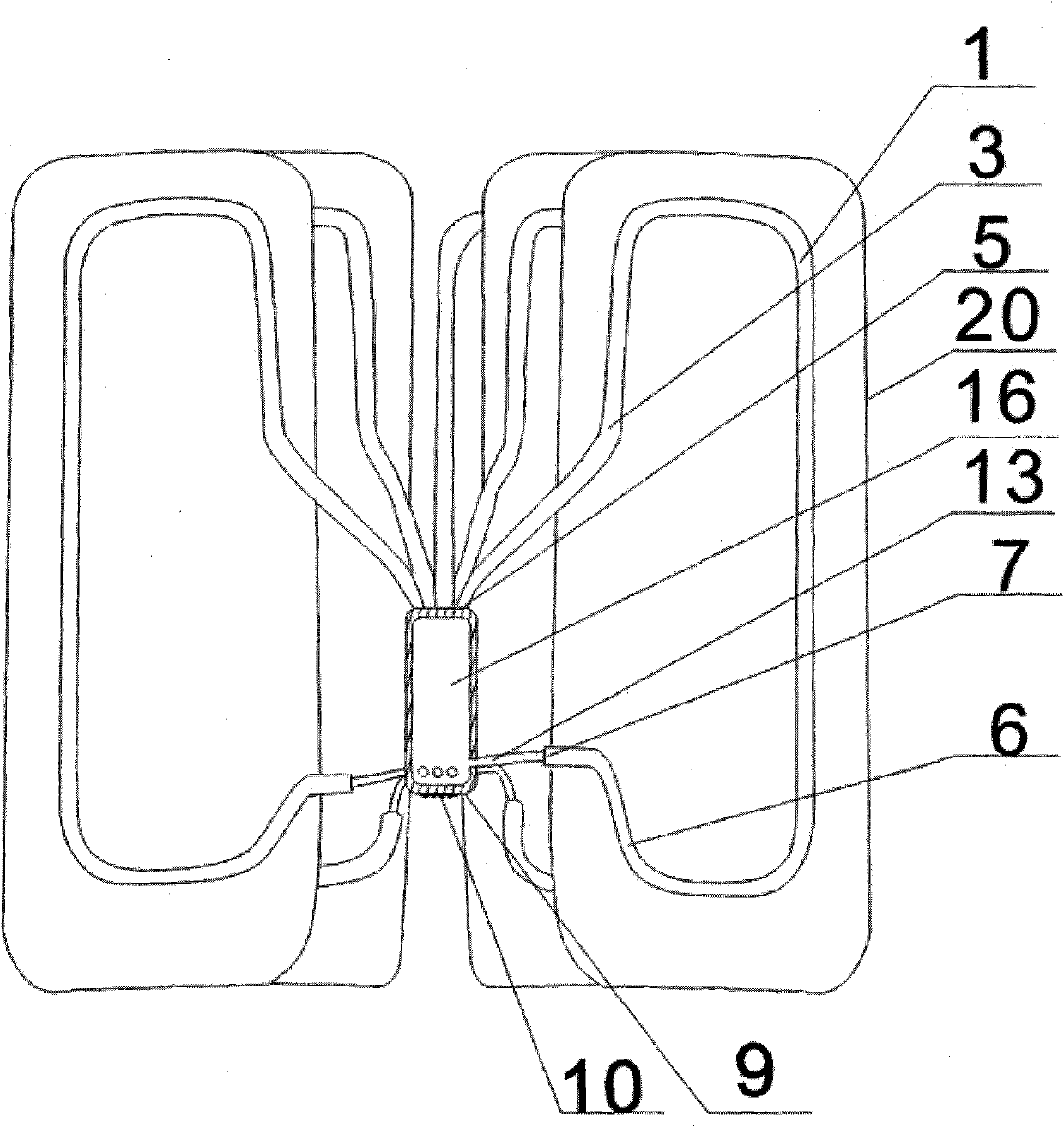
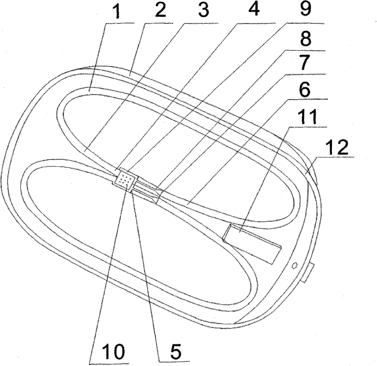
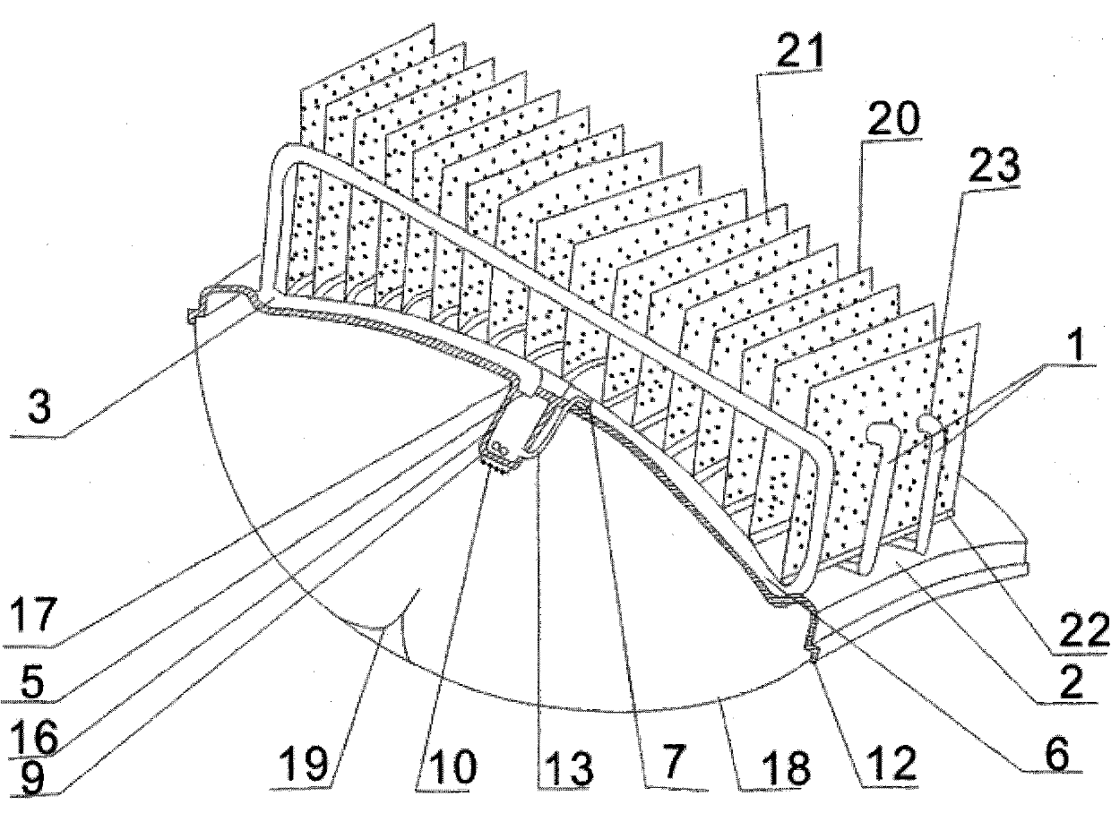
[0020] figure 1 The first embodiment of the present invention is viewed from above, and the circulating heat pipe 1 made of good conductor material is completely wrapped around the inner surface of the lamp housing 2, and the two are all welded to each other. The heating section 4 of the evaporating section 3 of the circulating heat pipe The pipe port of the heat pipe is the first port 5, and the end pipe port of the condensing section 6 of the circulation heat pipe is the end port 7, and the first and the end ports are connected through the throttle valve 8, thereby forming a sealed circulation heat pipe pipeline, and the heat of the heat circulation heat pipe The welding layer with good heat conduction is quickly transferred to the lamp housing stamped by good heat conduction material to form a matching evaporation section and condensation section. The lamp body shell forms an inclined angle with the horizontal plane, which is convenient for the condensed working fluid to use...


PUM


Abstract

The invention relates to a heat pump type circulation heat pipe radiator for emitting the heat of an integrated LED (Light-Emitting Diode) chip, which is characterized by being formed by welding and assembling a circulation heat pipe, a lamp shell, a working medium pump and radiating fins as elements; the head end of an evaporation zone of the radiator and the tail end of a condensation zone of the radiator are communicated by a throttle valve or a throttle pipe or communicated with the throttle pipe through the working medium pump to form a sealed circulation heat pipeline; the heat emitted from the LED chip is utilized to make a working medium boiled so as to form an evaporation high-pressure section; along with exchanging heat with the environment, a condensation low-pressure section is formed at the tail end of the circulation heat pipe, wherein the working medium generates phase change and pressure difference by utilizing the heat to push the working medium to circulate in one way in the circulation heat pipe; the heat exchange area is enlarged by utilizing the external space of the lamp shell; and the four elements are assembled into various types of radiators. The radiator is especially applicable to LED chips with high heat-flow density and high power, does not need a fan, ensures the low temperature rise of a node and takes the positive actions on energy saving and environment beautifying.

Description

Technical field [0001] The invention relates to a cooling device for distributing the heat of an integrated LED (Light Emitting Diode, English abbreviation for light-emitting diode) chip, especially a heat dissipation device capable of dissipating its high heat flux density and high-power heat without a fan, so as to keep the nodes of the LED chip at a uniform temperature rise Heat pump type circulating heat pipe radiator. Background technique [0002] At present, the heat sink used to dissipate the heat of highly integrated high-power LED chips is a well-known representative heat pipe radiator. Its working principle is: in the heat-receiving section of the heat pipe, the working fluid in it receives heat and boils and evaporates, and carries the heat to the condensation section. Exchange heat with the tube wall, the working fluid condenses and is absorbed by the siphon in the liquid-absorbing core, and flows back to the heating section by gravity and siphon force, forming a...

Claims


Application Information

Patent Timeline
IPC IPC(8): F21V29/02F21V17/00F21Y101/02F21V29/51
Inventor 吴鸿平
Owner 吴鸿平
Why Eureka
Try Eureka