Zero-debugging method of sensor for main control valve of steering engine actuator

A sensor and actuator technology, which is applied in the field of improvement of the method of zero adjustment of the main control valve sensor of the steering gear actuator, can solve the problems of rework, out-of-tolerance consistency of the output values ​​of the four channels of the sensor, assembly and debugging of the steering gear actuator Efficiency decline and other problems, to achieve the effect of improving assembly and debugging efficiency and improving assembly and debugging efficiency

Active Publication Date: 2010-12-15
FLIGHT AUTOMATIC CONTROL RES INST
View PDF6 Cites 6 Cited by
  • Summary
  • Abstract
  • Description
  • Claims
  • Application Information

AI Technical Summary

Problems solved by technology

The disadvantage is that when the main control valve is installed on the steering gear actuator, the consistency of the output values ​​of the four cha

Method used


Image

  • Zero-debugging method of sensor for main control valve of steering engine actuator
  • Zero-debugging method of sensor for main control valve of steering engine actuator

Examples


Embodiment 1

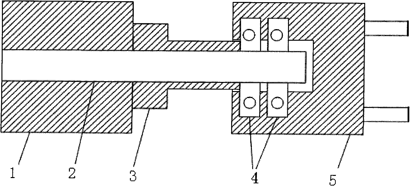
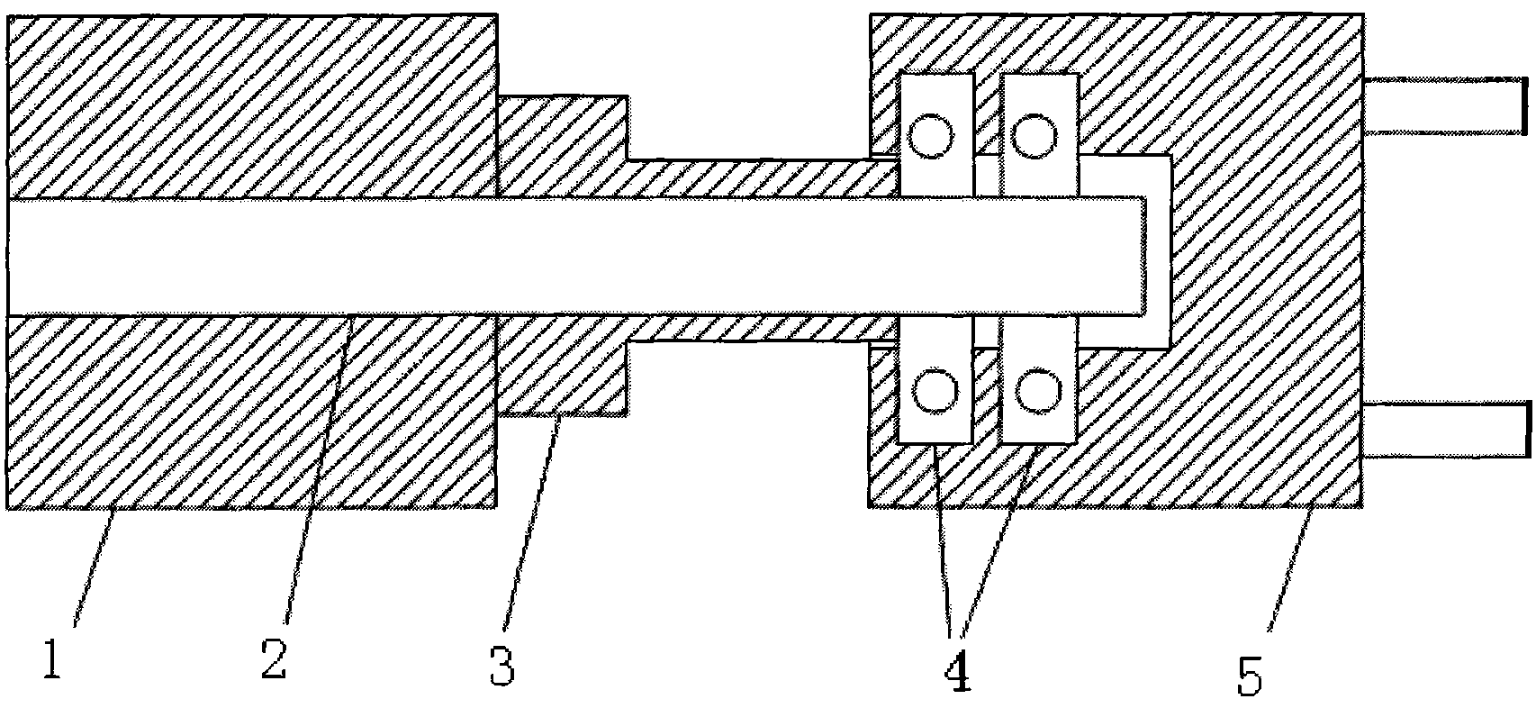
[0023] The outer diameter of the flexible rod 2 is d = 4764.2 μm, the sensor bushing 3D = 4766.5 μm, D-d = 2.3 μm. Use step 2 to rotate the flexible rod 2 one circle, measure the variation Δt1 of the output values ​​of the four channels of the sensor, Δt1=A=B=C=D=26 μm; continue to adjust the angle of the sensor bushing 3; remove the sensor 5, Rotate the sensor bushing 3 clockwise by 90°, and then reinstall the sensor 5; rotate the flexible rod 2 once, measure the variation Δt2 of the output values ​​of the four channels of the sensor, Δt2=A=B=C=D=18μm, and continue to adjust The angle of the sensor bushing 3; remove the sensor 5, continue to rotate the sensor bushing 3 90° clockwise, and then reinstall the sensor 5; rotate the flexible rod 2 one circle, and measure the variation of the output value of the four channels of the sensor Δt3 , Δt3=A=B=C=D=14 μm≤15 μm. Then the zero position debugging of the sensor 5 was successfully completed.

Embodiment 2

[0025] The outer diameter of the flexible rod 2 is d = 4764.2 μm, the sensor bushing 3D = 4765.8 μm, D-d = 1.6 μm. Use step 2 to rotate the flexible rod 2 one circle, measure the variation Δt1 of the output values ​​of the four channels of the sensor, Δt1=A=B=C=D=17 μm; continue to adjust the angle of the sensor bushing 3; remove the sensor 5, Rotate the sensor bushing 3 clockwise by 90°, and then reinstall the sensor 5; rotate the flexible rod 2 once, and measure the variation Δt2 of the output values ​​of the four channels of the sensor, Δt2=A=B=C=D=11μm≤15μm, The zero position debugging of the sensor 5 is completed.

Embodiment 3

[0027] The outer diameter of the flexible rod 2 is d = 4764.5 μm, the sensor bushing 3D = 4765.7 μm, D-d = 1.2. Use step 2 to rotate the flexible rod 2 one circle, measure the variation Δt1 of the output values ​​of the four channels of the sensor, Δt1=A=B=C=D=11μm≤15μm, and the sensor 5 has been adjusted for zero position.


PUM

PropertyMeasurementUnit
Outer diameteraaaaaaaaaa

Abstract

The invention belongs to a sensor debugging technique and relates to the improvement on a zero-debugging method of a sensor for a main control valve of a steering engine actuator. The zero-debugging method is used for carrying out mechanical zero debugging to a sensor [5] and comprises the following steps of: adjusting a gap between a flexible rod [2] and a sensor bush [3]; measuring the change amounts of four-channel output values of the sensor [5]; and adjusting the angle of the sensor bush [3]. The zero-debugging method can solve the problem of the ultra-poor consistency of the four-channel output values of the sensor after the main control valve is installed on the steering engine actuator and improve the assembling and debugging efficiency of the steering engine actuator.

Description

technical field [0001] The invention belongs to the sensor debugging technology, and relates to the improvement of the zero adjustment method for the main control valve sensor of the steering gear actuator. Background technique [0002] The main control valve of a certain type of steering gear actuator is the heart of the steering gear, and whether its performance is stable is one of the factors that affect the performance of the steering gear. For the connection relationship between the main control valve and the installed four-degree sensor, see figure 1 . A flexible rod 2 is installed in the central hole of the spool 1. The sensor bush 3 is sleeved on the flexible rod 2 and is located on the right side of the spool 1. The right end of the flexible rod 2 is connected with the sensor 5 through the bearing 4 as a whole. At present, the zero adjustment method of the sensor is: adopt the direct mechanical zero position debugging method, that is, realize the zero adjustment o...

Claims


Application Information

Patent Timeline
IPC IPC(8): G01D3/06
Inventor 王升刘宇
Owner FLIGHT AUTOMATIC CONTROL RES INST
Why Eureka
Try Eureka