Automatic detection device and positioning method for weld joint at safe end of nuclear reactor pressure vessel

Active Publication Date: 2010-12-15
CGNPC INSPECTION TECH +2
View PDF6 Cites 35 Cited by
  • Summary
  • Abstract
  • Description
  • Claims
  • Application Information

AI Technical Summary

Problems solved by technology

The advantage of this type of equipment is that it is easy to locate between the coordinate system of the equipment itself and the coordinate system of the pressure vessel, and it is convenient for the inspection tool to quickly locate the part to be inspected; however, it has the disadvantage that the equipment is bulky and occupies resources in the nuclear island (such as the site and ring cranes). Obvious disadvantages such as severe, long installation and exit times
In addition, when such equipment performs inspection work in the pressure vessel, it generally does not allow other equipment to perform inspection work in parallel, which is not conducive to the overall optimization of the pressure vessel inspection time window
[0005] At the same time, since the area to be detected is a substantially cylindrical area, the ultrasonic probe is inserted into the nozzle for inspection, and the scanning data fed back by the ultrasonic probe should correspond to its scanning position, while the existing equipment, which is fixed There is a certain randomness in the nozzle, and there is a certain deviation between the axial and circumferential positions and the ideal situation. This deviation may exceed the allowable error range of the inspection, so that the reliability of the inspection results cannot be guaranteed. create certain safety hazards

Method used


Image

  • Automatic detection device and positioning method for weld joint at safe end of nuclear reactor pressure vessel
  • Automatic detection device and positioning method for weld joint at safe end of nuclear reactor pressure vessel
  • Automatic detection device and positioning method for weld joint at safe end of nuclear reactor pressure vessel

Examples


Embodiment Construction

[0047] Below in conjunction with accompanying drawing, illustrate in detail the specific content of the preferred implementation of the ultrasonic inspection equipment of the present invention:

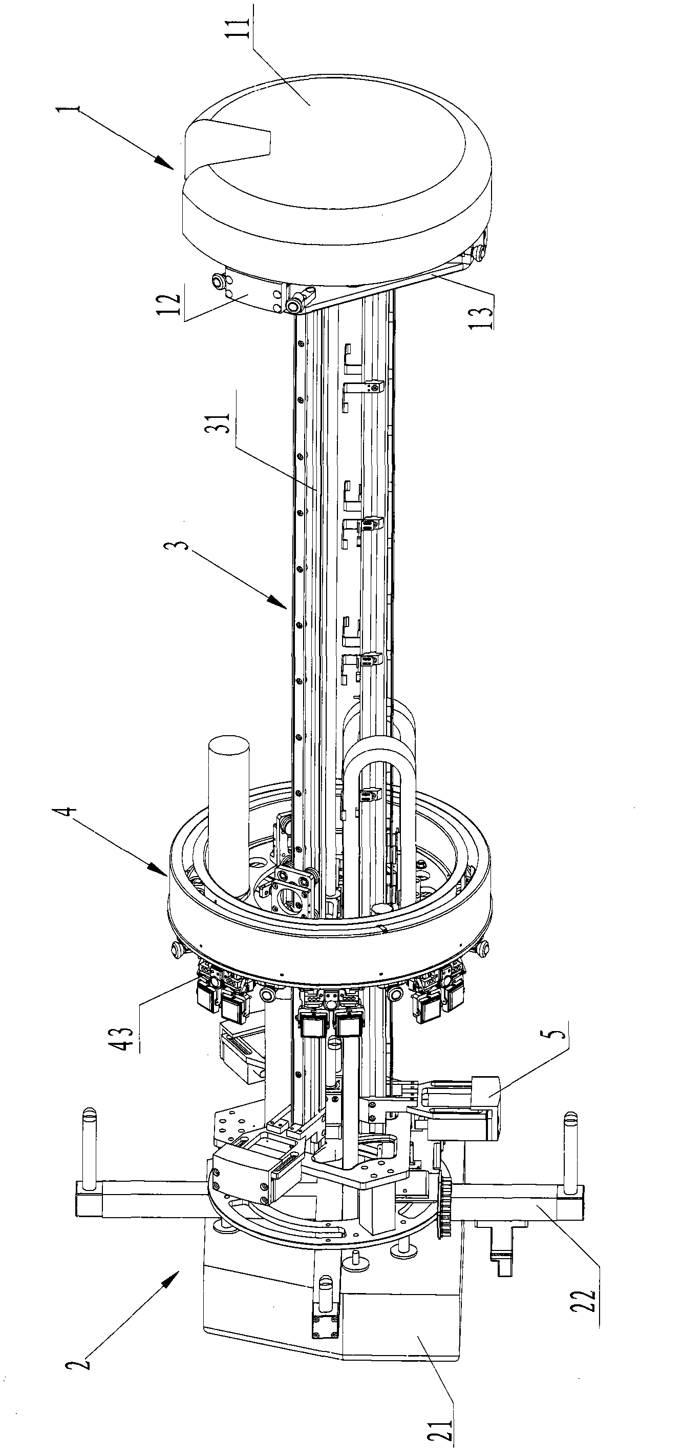
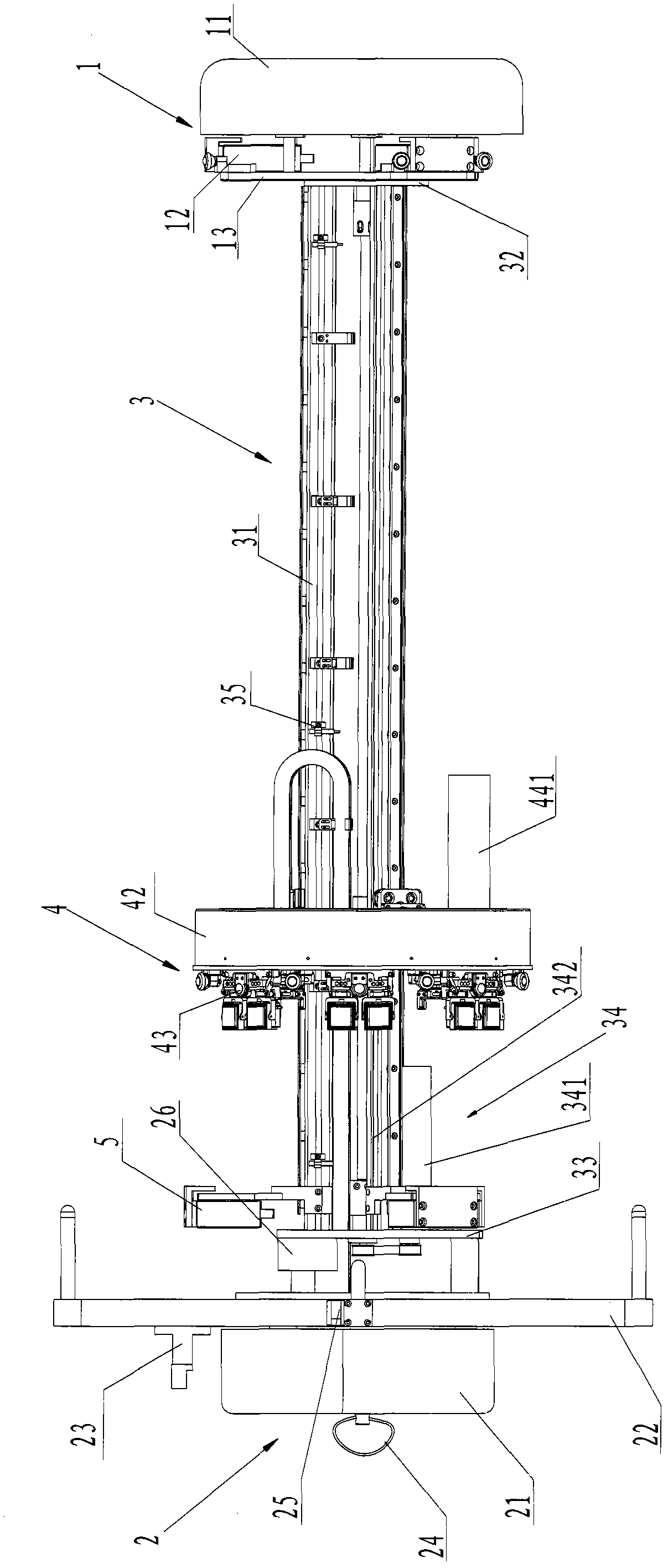
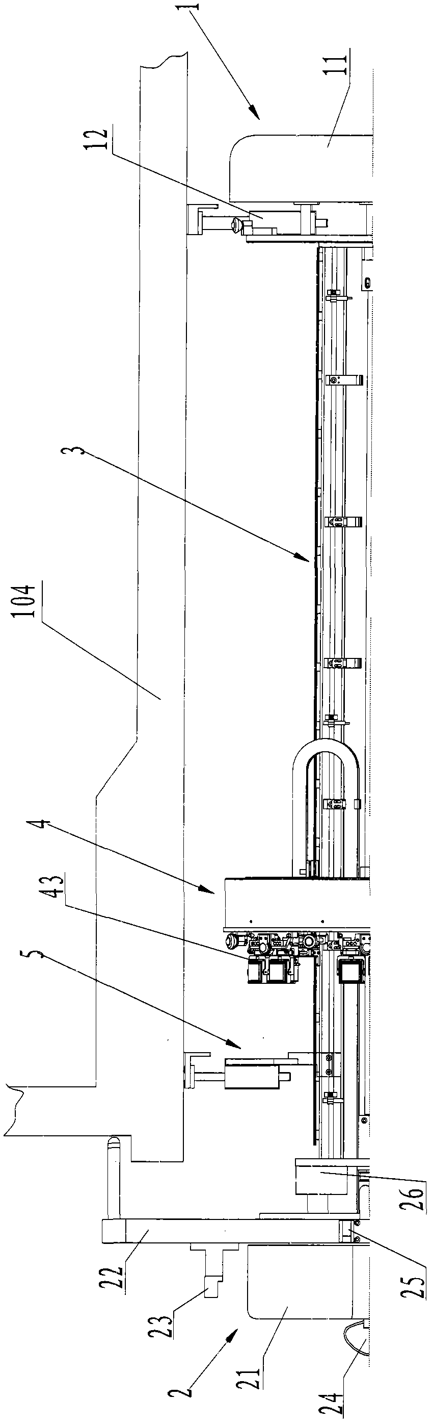
[0048] Since the ultrasonic inspection equipment of the present invention is inserted into the nozzle of the pressure vessel for detection, first define the viewing direction of the equipment in order to explain its structural features more clearly. We first enter the end of the nozzle with the equipment called the front end, such as figure 1 , figure 2 On the right side shown, the other end where the equipment is finally positioned on the inner wall of the pressure vessel cylinder is called the rear end, such as figure 1 , figure 2 shown on the left.

[0049] Figure 1 to Figure 4 It shows an ultrasonic inspection device preferably implemented according to the present invention, which is mainly composed of a front support module 1, a rear support module 2, a guide rail assemb...


PUM


Abstract

The invention relates to automatic detection equipment and a positioning method for a weld joint at safe end of nuclear reactor pressure vessel. The automatic detection equipment comprises a bracket body, a scanning device and a positioning mechanism, wherein the positioning mechanism comprises a supersonic distance measurement sensor for detecting the distance between the front end of an end face strut and the wall of a cylinder, a horizontal inclinometer user for detecting the inclination angle of the detection equipment in X-axis direction, an axial approach switch for fixing the initial position of the scanning device in Y-axis direction and a circumferential approach switch for fixing the initial position of a supersonic probe frame in X-axis direction. After the rough positioning and the accurate positioning in axial direction and circumferential direction, scanning work can be performed. By the invention, the problem that scanning feedback data is not in correspondence with scanning positions, caused by probably existed axial or circumferential offset and the zero position offset of the supersonic probe frame in a pipe nozzle, can be overcome, thereby ensuring the readability of detection results. The whole process is controlled automatically and operated very conveniently; and thus, the invention has grater promotion and application values.

Description

technical field [0001] The invention relates to the field of detection equipment for in-service / pre-service inspection of reactor pressure vessels of nuclear power plants, in particular to the inspection equipment and positioning method for the pressure vessel water outlet and water inlet nozzle positions. Background technique [0002] The nuclear reactor pressure vessel is one of the most important components of a nuclear power plant. It is used to fix, support and contain the core and all reactor internals. It is the only large-scale component that cannot be replaced during the entire life of the nuclear power plant. The quality of the nuclear reactor pressure vessel is the key to ensure the normal and safe operation of the nuclear power system. Figure 16 The shown nuclear reactor pressure vessel has a main body of a cylinder 101, the upper part of the cylinder 101 is connected with a hemispherical upper head (not shown in the figure) and a flange 102 through a bolt assemb...

Claims


Application Information

Patent Timeline
Patent Type & Authority Applications(China)
IPC IPC(8): G21C17/00G01N29/265G01N29/04
CPCY02E30/30
Inventor 刘金宏李明吴健荣陈怀东吕天明
Owner CGNPC INSPECTION TECH
Why Eureka
Try Eureka