Method and device for automatically isolating and positioning earth faults of Dc system

A ground fault, DC system technology, applied in the direction of fault location, emergency protection circuit devices, electrical components, etc., can solve the problems that ground faults cannot be isolated, cannot be located, methods and devices, etc., so as to reduce the impact and facilitate maintenance and operation personnel to master , The effect of reducing the time leading the way

Inactive Publication Date: 2010-12-15
STATE GRID CORP OF CHINA +1
View PDF5 Cites 21 Cited by
  • Summary
  • Abstract
  • Description
  • Claims
  • Application Information

AI Technical Summary

Problems solved by technology

[0013] The object of the present invention is to propose a method and device for automatically isolating and locating ground faults in DC systems of substations, aiming at the defects of existing methods and devices for dealing with ground faults in DC systems that cannot be isolated or located. , isolate the fault branch from the DC system, ensure the normal operation of the non-fault circuit without interference, monitor each branch in real time online, and realize the location of multiple fault points. The device is composed of an isolated power supply, an insulation monitoring device, Composed of switching control device, communication module and upper PC; each DC power unit branch is equipped with a DC insulation monitoring device, the communication module is connected to the branch insulation monitoring device, and its output signal line is connected to the upper PC through the bus system , the switching control device and the output control line are connected to the drive output unit, and then connected to the relay switching element through the transistor switching element

Method used


Image

  • Method and device for automatically isolating and positioning earth faults of Dc system
  • Method and device for automatically isolating and positioning earth faults of Dc system
  • Method and device for automatically isolating and positioning earth faults of Dc system

Examples


Embodiment Construction

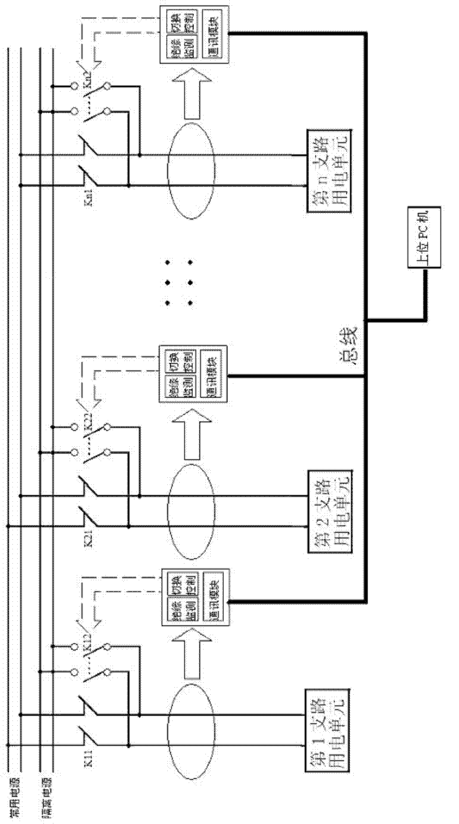
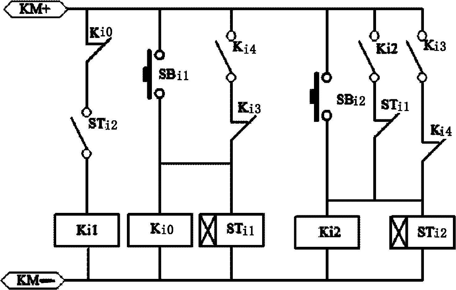
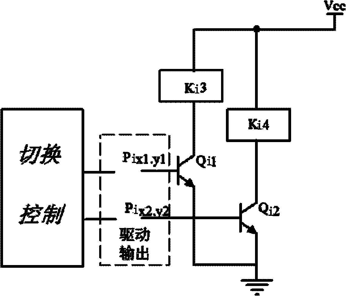
[0036] The markings in the drawings, with figure 1 Among them, K11, K21, Kn1—the common power supply is connected to the 1st, 2nd and nth branch control relay normally closed contacts, K12, K22, Kn2——the isolated power supply is connected to the 1st, 2nd to nth branch The normally open contact of the control relay of the branch circuit; figure 2Among them, Ki0——relay coil and its normally closed contact, Ki1, Ki2——the i (i=1, 2...n) branch relay coil and its normally open contact, Ki3, Ki4——the i Branch relay normally open or normally closed contact, SBi1, SBi2—manual switch button switch for the i branch, STi1, STi2—time delay relay and its contact for the i branch, KM+—control power positive pole , KM- —— negative pole of control power supply; attached image 3 Among them, Vcc-control power supply, Ki3, Ki4--relay coil on the i-th branch, Qi1, Qi2--transistor switching elements on the i-th branch, Pix1y1, Pix2y2--drive output signal of the i-th branch.

[0037] Embodimen...


PUM


Abstract

The invention relates to a device for automatically isolating and positioning earth faults of a Dc system, which overcomes the defects that the conventional device can only monitor specific earth-return circuits or branch circuits of a DC return circuit earth, but cannot isolate fault return circuits from the DC system so as to influence safe operation of normal return circuits because of fault operation of the fault return circuits. The device supplies power to power consumption units by using mutually independent dual DC power supplies and switches fault branch circuit power units from a common power supply to an isolated power supply. All the branch circuits are provided with on-line insulation monitoring device; a communication module is connected with the insulation monitoring device; output signals are connected with an upper PC machine; and the upper PC machine controls all the branch circuits to be isolated sequentially so as to find fault points, receives, stores and comprehensively analyzes monitoring data of all the branch circuits, reports the earth faults of the DC system and displays earth return circuit numbers and earth points in the branch circuits.

Description

technical field [0001] The invention relates to a method and a device for automatically isolating and locating a grounding fault of a DC system of a substation, and belongs to the technical field of operation and maintenance of power station equipment in a power system. Background technique [0002] The DC system in the substation provides DC power for control, signal, relay protection, automatic devices and emergency lighting, etc. It also provides reliable operating power for operations. The reliability of the DC system plays a vital role in the safe operation of the substation. The important role is to guarantee the safe operation of the substation. Due to the wide distribution of the DC system in the substation, many exposed parts, many cables, and long lengths, it is easily corroded by dust and moisture, which reduces the insulation of some weakly insulated components, and even causes DC grounding due to insulation damage. Analysis of DC grounding The reasons are gener...

Claims


Application Information

Patent Timeline
Patent Type & Authority Applications(China)
IPC IPC(8): H02H7/22G01R31/08
Inventor 蔡骏峰
Owner STATE GRID CORP OF CHINA
Why Eureka
Try Eureka