

Guide wire
A technology of guide wires and linear parts, which is applied in the field of guide wires and can solve the problems of poor operability of guide wires
- Summary
- Abstract
- Description
- Claims
- Application Information
AI Technical Summary
Problems solved by technology
Method used
Image

Examples
no. 1 Embodiment approach
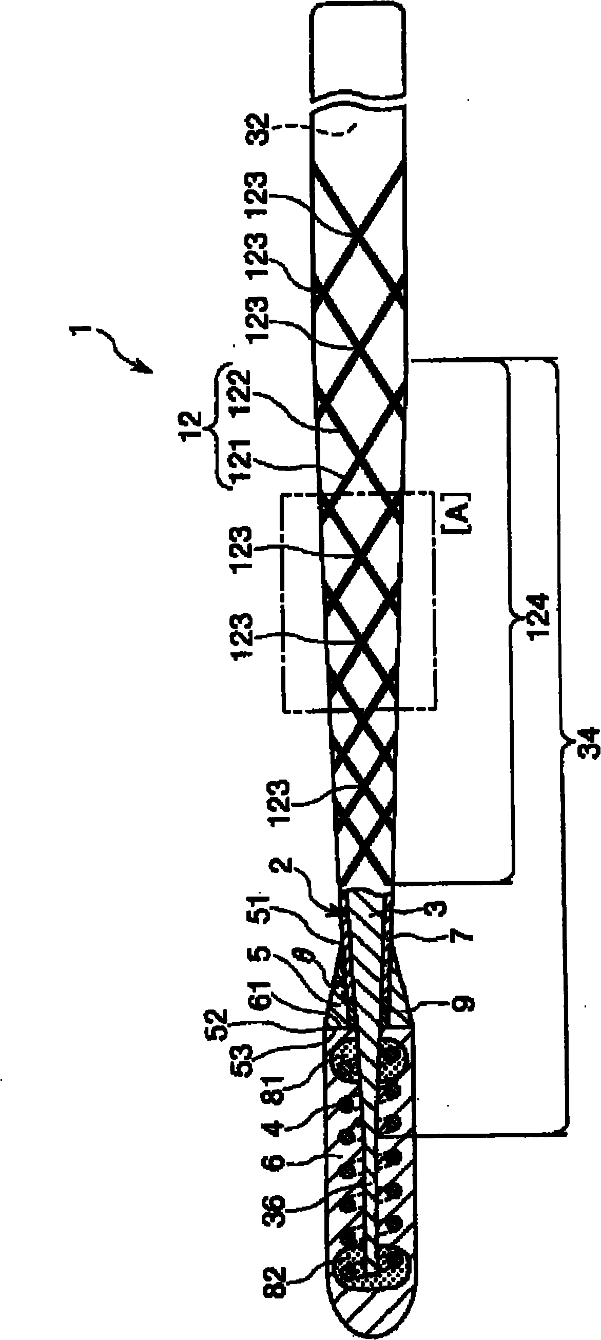
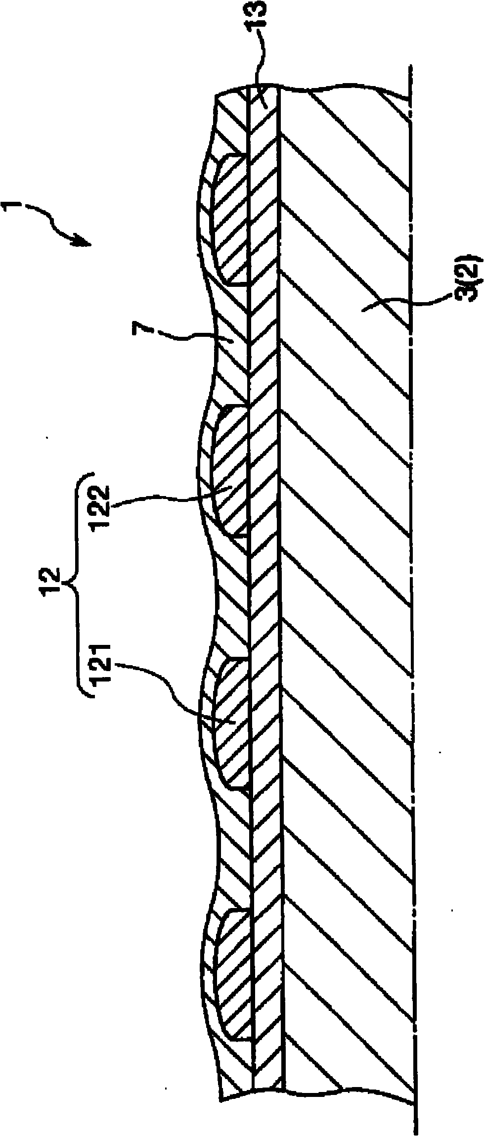
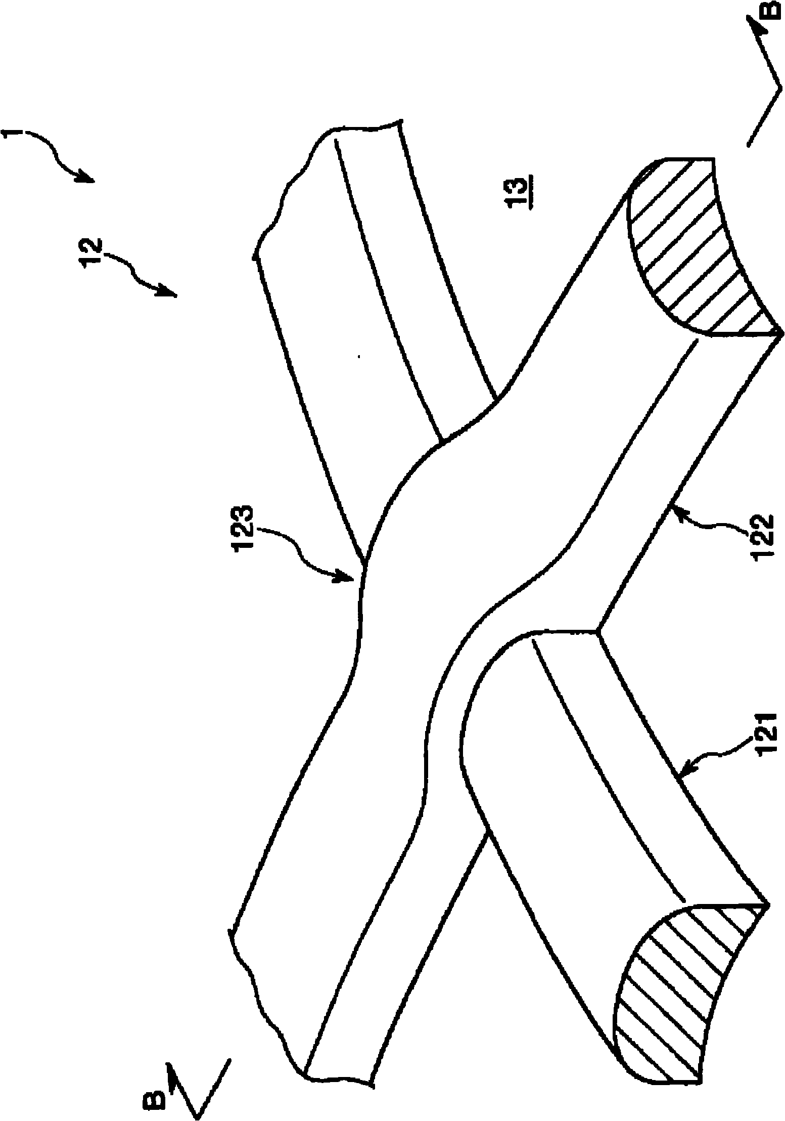
[0058] figure 1 It is a partial longitudinal sectional view showing the first embodiment of the guide wire of the present invention; figure 2 for figure 1 The longitudinal section of the area [A] surrounded by dotted lines in ; image 3 for figure 1 A perspective view of the markers in the guideline shown; Figure 4 for image 3 B-B line sectional view in ; Figure 5 to express figure 1 Diagram of the marker change process as the guideline shown rotates around its axis; Figure 6 to express figure 1 A plot of the marker change process as the guideline is shown moving along its axis. It should be noted that, for the convenience of explanation, the following figure 1 , figure 2 , Figure 5 and Figure 6 middle( Figure 7 , Figure 8 The same is true in ), the right side is called "basal end", and the left side is called "front end". Also, for ease of understanding, in figure 1 In , the length direction of the guide line is shortened, and the width directio...
no. 2 Embodiment approach
[0167] Figure 7 It is a side view showing a second embodiment of the guide wire of the present invention.
[0168] Hereinafter, the second embodiment of the guide wire of the present invention will be described with reference to this figure, but the description will focus on the differences from the above-mentioned embodiment, and the description of the same matters will be omitted.
[0169] This embodiment is the same as the above-mentioned first embodiment except that the formation state (formation condition) of the first linear portion and the second linear portion is different.
[0170] exist Figure 7 In the marker 12A of the guide wire 1A shown, the magnitude of the helical pitch of the first linear portion 121 and the helical pitch of the second linear portion 122 are different from each other. In the illustrated configuration, the helical pitch of the second linear portion 122 is set to be smaller than the helical pitch of the first linear portion 121 .
[0171] Th...
no. 3 Embodiment approach
[0175] Figure 8 It is a side view showing a third embodiment of the guide wire of the present invention.
[0176] Hereinafter, a third embodiment of the guide wire of the present invention will be described with reference to this figure, but the description will focus on the differences from the above-mentioned embodiment, and the description of the same items will be omitted.
[0177] This embodiment is the same as the above-mentioned first embodiment except that the formation state (formation condition) of the first linear portion and the second linear portion is different.
[0178] exist Figure 8 In the mark 12B of the guide wire 1B shown, the respective widths of the first linear portion 121 and the second linear portion 122 gradually decrease toward the distal end direction. The portion where the width decreases (decreasing width portion) is preferably formed in the tapered portion 34 of the core body 2 . By confirming the above-mentioned portion, it can be grasped t...
PUM
 Abstract
Description
Claims
Application Information