Floating LNG storage and re-gasification unit and method for re-gasification of LNG on said unit

A regasification and floating technology, applied in the direction of container discharge method, mechanical equipment, container filling method, etc., can solve the problem of consuming large energy and extra waste gas

Inactive Publication Date: 2010-12-15
WARTSILA FINLAND OY
View PDF0 Cites 13 Cited by
  • Summary
  • Abstract
  • Description
  • Claims
  • Application Information

AI Technical Summary

Problems solved by technology

These known techniques consume large amounts of energy and generate unnecessary additional exhaust gases

Method used


Image

  • Floating LNG storage and re-gasification unit and method for re-gasification of LNG on said unit
  • Floating LNG storage and re-gasification unit and method for re-gasification of LNG on said unit
  • Floating LNG storage and re-gasification unit and method for re-gasification of LNG on said unit

Examples


Embodiment Construction

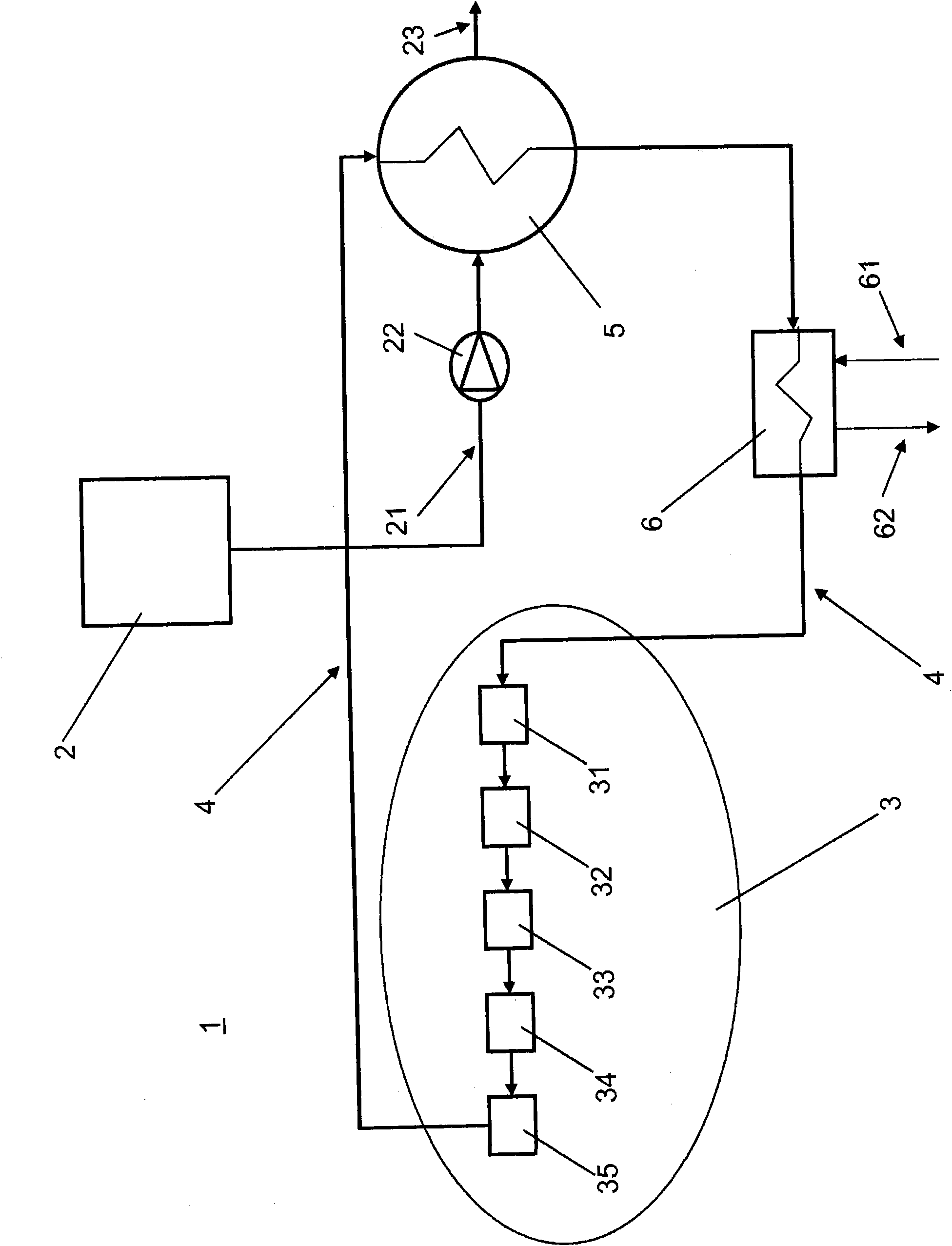
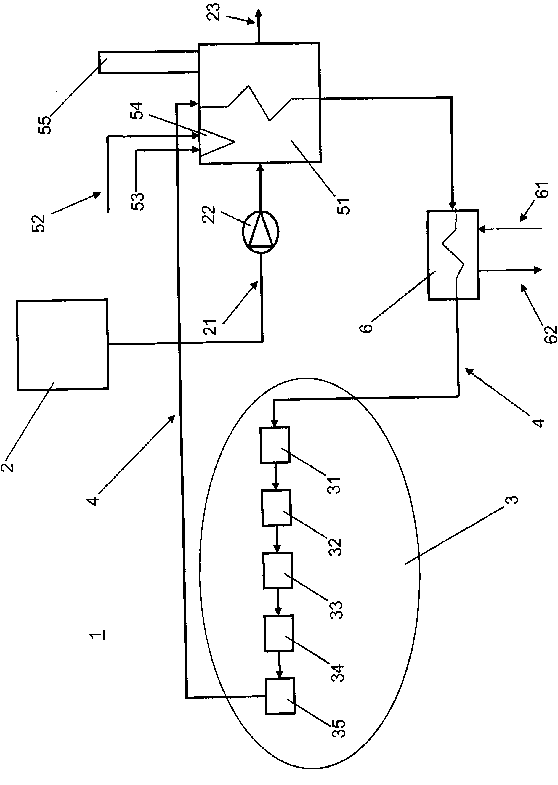
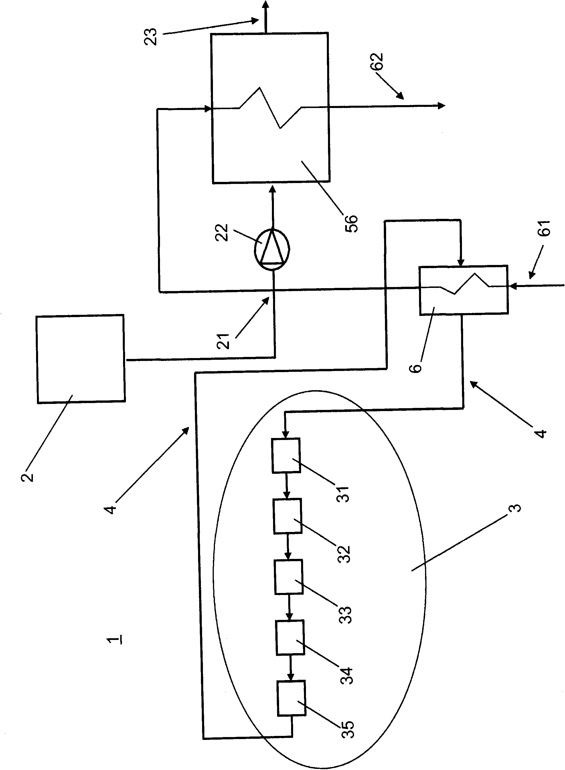
[0018] exist figure 1 In , the floating LNG storage and regasification unit (FSRU) is collectively denoted by reference numeral 1 . FSRUs are usually permanently moored terminals in the form of vessels without propulsion. The FSRU is provided with power generation equipment (in this embodiment, a power plant denoted by reference numeral 3 ), regasification equipment, hotel consumption equipment, and LNG storage equipment and LNG gasification equipment. The FSRU is also typically provided with a gas supply (not shown) for connection to appropriate pipelines for transporting the gasified LNG to shore and then to end consumption.

[0019] The FSRU includes an LNG storage tank 2 connected to a gasification device 5 through a supply line 21 provided with a high-pressure pump 22 . The gasification device 5 is provided as a heat exchanger for receiving LNG in liquefied form from an LNG storage tank and discharging it through a discharge line 23 after heating it into natural gas.

...


PUM


Abstract

A floating LNG storage and re-gasification unit, which comprises a LNG storage tank (2), a power plant (3), and a vaporizing unit (5), which power plant is arranged to generate heat for the vaporizing unit. The power plant (3) comprises a number of heat sources, which are connected to a single heating circuit (4). In order to increase the overall efficiency of said unit, the single heating circuit is directly or indirectly connected to the vaporizing unit (5).

Description

technical field [0001] The present invention relates to a floating LNG storage and regasification facility as described in the preamble of claim 1, which comprises an LNG storage tank, a power unit and a gasification device, and the power unit provides thermal energy to the gasification device. The present invention also relates to a method for LNG regasification on the floating LNG storage and regasification facility as described in the preamble of claim 9 . Background technique [0002] A floating liquefied natural gas (LNG) storage and regasification unit (FSRU) is a permanently moored LNG input terminal. FSRUs are therefore usually not fitted with propulsion. So-called LNG carriers are used to transport and supply LNG to FSRUs for storage. After the LNG is loaded into the FSRU, it is pumped to the regasification facility, and the gasified natural gas (NG) is usually transported from the regasification facility to the shore through underwater pipelines and then to the t...

Claims


Application Information

Patent Timeline
Patent Type & Authority Applications(China)
IPC IPC(8): F17C9/04F17C5/06
CPCF17C2223/0161F17C2270/0123F17C2260/035F17C2221/033F17C2227/0323F17C2225/035F17C5/06F17C2223/033F17C2265/05F17C2227/0135F17C2270/0113F17C9/04Y02T70/72F17C2227/0393F17C2227/0327F17C2225/0123
Inventor 马库斯·埃尔斯特伦
Owner WARTSILA FINLAND OY
Why Eureka
Try Eureka