Machine tool for processing workpieces

A technology for processing workpieces and machine tools. It is applied in the direction of metal processing machinery parts, metal processing, metal processing equipment, etc. It can solve the problems of only small flexibility and limited processing space, and achieve the effect of modular structure and compact structure.

Inactive Publication Date: 2010-12-22
许勒·惠勒有限公司
View PDF6 Cites 19 Cited by
  • Summary
  • Abstract
  • Description
  • Claims
  • Application Information

AI Technical Summary

Problems solved by technology

The disadvantage of this machine tool is that its machining space is limited laterally by the side walls and thus offers only a small degree of flexibility during workpiece machining

Method used


Image

  • Machine tool for processing workpieces
  • Machine tool for processing workpieces
  • Machine tool for processing workpieces

Examples


Embodiment Construction

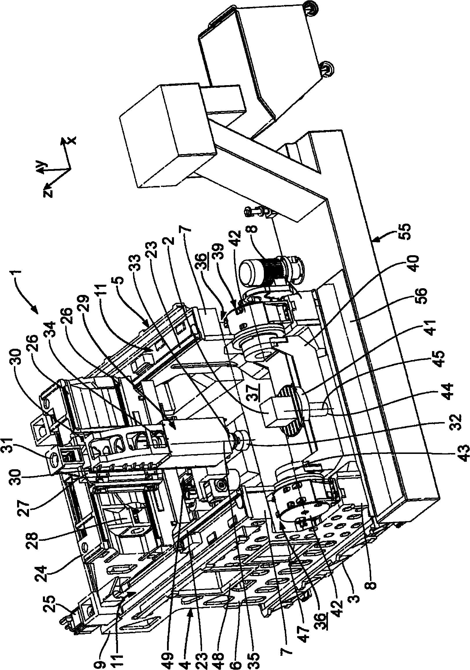
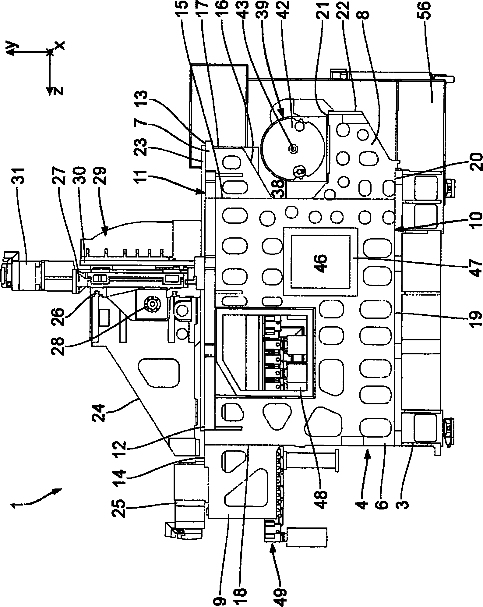
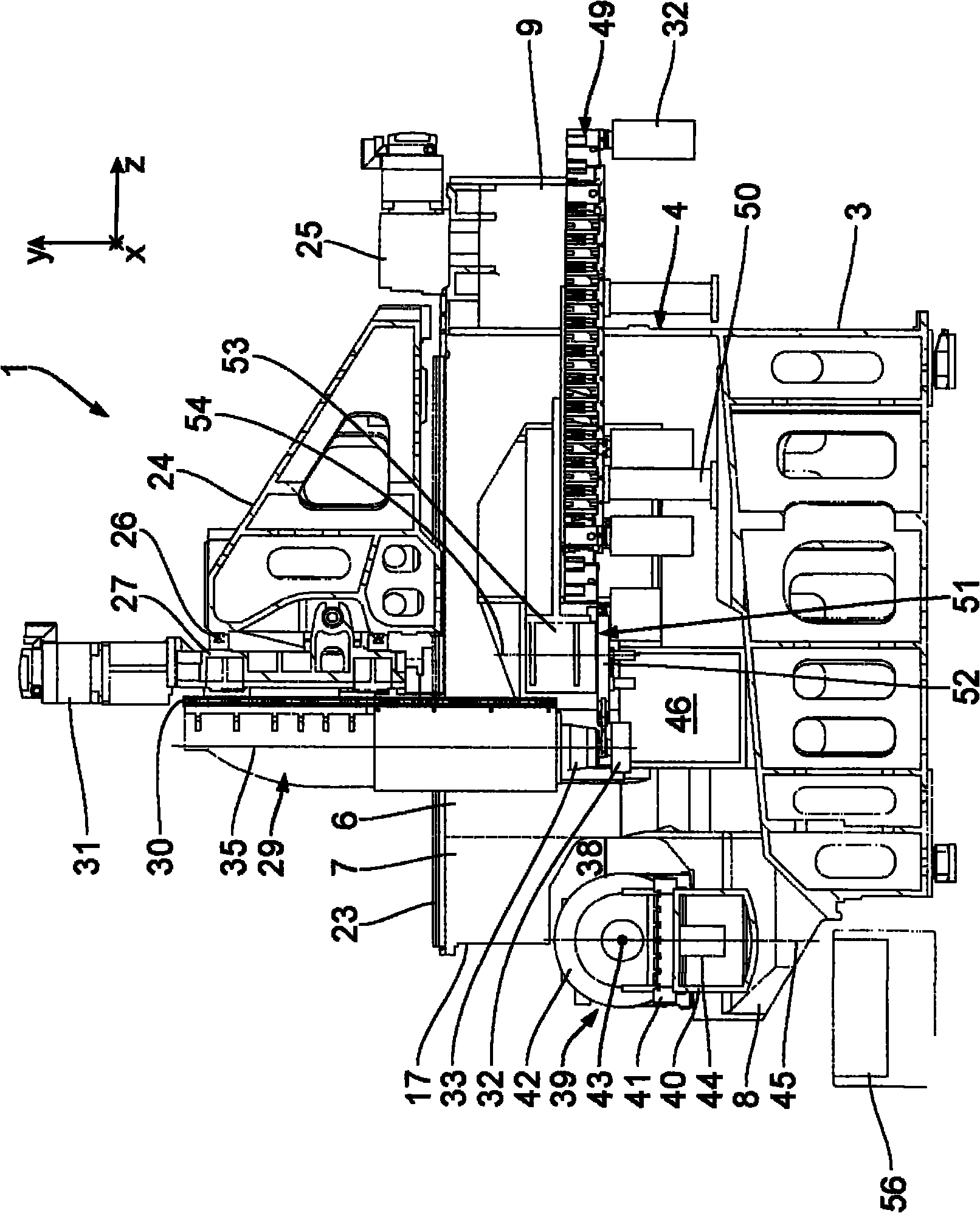
[0039] Refer below Figures 1 to 3 A first exemplary embodiment of the present invention is described. A machine tool 1 for machining a metal workpiece 2 comprises a machine base 3 on which a first side wall 4 and a second side wall 5 mirrored thereto are arranged. The side walls 4, 5 are spaced apart from each other in the horizontal x-direction and extend substantially parallel to a y-z plane defined by the vertical y-direction and the horizontal z-direction. The x, y, and z directions form a Cartesian coordinate system.

[0040] The side walls 4 , 5 each comprise a substantially rectangular base body 6 on which the displacement extension 7 , the bearing extension 8 and the support extension 9 are formed as one part. figure 2 By way of example, the rectangular base body 6 of the side wall 4 is shown in dashed lines. Each of the side walls 4 , 5 is fastened to the frame 3 via their side wall bottom side 10 . The side wall top side 11 remains free. Each side wall top sid...


PUM


Abstract

A machine tool for achieving a high degree of flexibility during workpiece processing comprises a machine bed with side walls arranged thereon, which respectively comprise a basic body with a front overhanging projection arranged thereon. On the side walls a tool spindle is arranged to be linearly movable by means of slides. Underneath the front overhanging projections a processing space is formed for the workpiece processing, in which a workpiece positioning unit is arranged. The processing space underneath the front overhanging projections is freely accessible, whereby depending on the processing task different workpiece positioning units can be arranged therein.

Description

technical field [0001] The invention relates to a machine tool for processing workpieces, which has: a machine base; Each has a top side of the side wall; a z-slide which is arranged on the side wall in the region of the top side of the side wall and which can be moved on the side wall in the horizontal z-direction by means of a z-drive motor ; the x-sliding seat, the x-sliding seat is arranged on the z-sliding seat and can move along the horizontal x-direction on the z-sliding seat by means of the x-direction drive motor; A rotationally driven tool spindle which is suspended on the x-slide and can be moved in the vertical y-direction on the x-slide by means of a y-drive motor. Background technique [0002] Such a machine tool is known, for example, from EP 0 568 798 B9. The machine tool includes a machine base with two side walls arranged parallel to each other, on which a multi-axis slide is movably arranged. A vertically suspended operating spindle is fixed on the mult...

Claims


Application Information

Patent Timeline
Patent Type & Authority Applications(China)
IPC IPC(8): B23Q39/02B23Q1/01B23Q16/00B23Q3/155
CPCB23Q1/015B23Q1/012Y10T29/5196Y10T82/2511Y10T82/2531Y10T409/30392Y10T409/304088Y10T409/305264Y10T409/305824Y10T409/306104Y10T409/307168Y10T409/308288Y10T409/308792Y10T409/309576Y10T483/1705Y10T483/1793
Inventor M·I·梅达尔W·霍恩B·鲍斯W·豪斯J·科里施克H·朗
Owner 许勒·惠勒有限公司
Why Eureka
Try Eureka