
Pneumatic tire

一种充气轮胎、轮胎的技术,应用在轮胎零部件、轮胎胎面/胎面花纹、运输和包装等方向,能够解决不均匀磨损、干燥路面操纵稳定性能恶化、花纹块刚性降低等问题,达到提高雪上性能、防止操纵稳定性能的显著恶化、良好排雪性能的效果

Active Publication Date: 2010-12-22
SUMITOMO RUBBER IND LTD
View PDF7 Cites 15 Cited by
  • Summary
  • Abstract
  • Description
  • Claims
  • Application Information

AI Technical Summary

Problems solved by technology

[0003] However, multiple sipes or full-open sipes with both ends connected to the main groove, etc., have the problem of lowering the rigidity of the block, which tends to cause deterioration of steering stability on dry road surfaces or uneven wear.

Method used


Image

  • Pneumatic tire
  • Pneumatic tire
  • Pneumatic tire

Examples


Embodiment

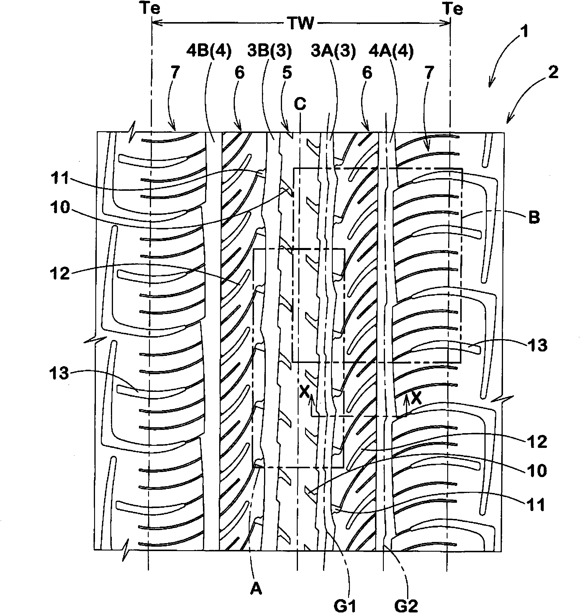
[0069] In order to confirm the effect of the present invention, a trial production with figure 1 195 / 65R15 passenger car radial tire with the pattern and specifications in Table 1. Furthermore, the tire was mounted on a Japanese-made 4WD vehicle with a displacement of 3500 cc at an internal pressure of 200 kPa, and the driving performance on snow and the uneven wear resistance were tested. All are the same except for the parameters shown in Table 1.

[0070] In addition, the common specifications are as follows.

[0071] Tread contact width TW: 162mm

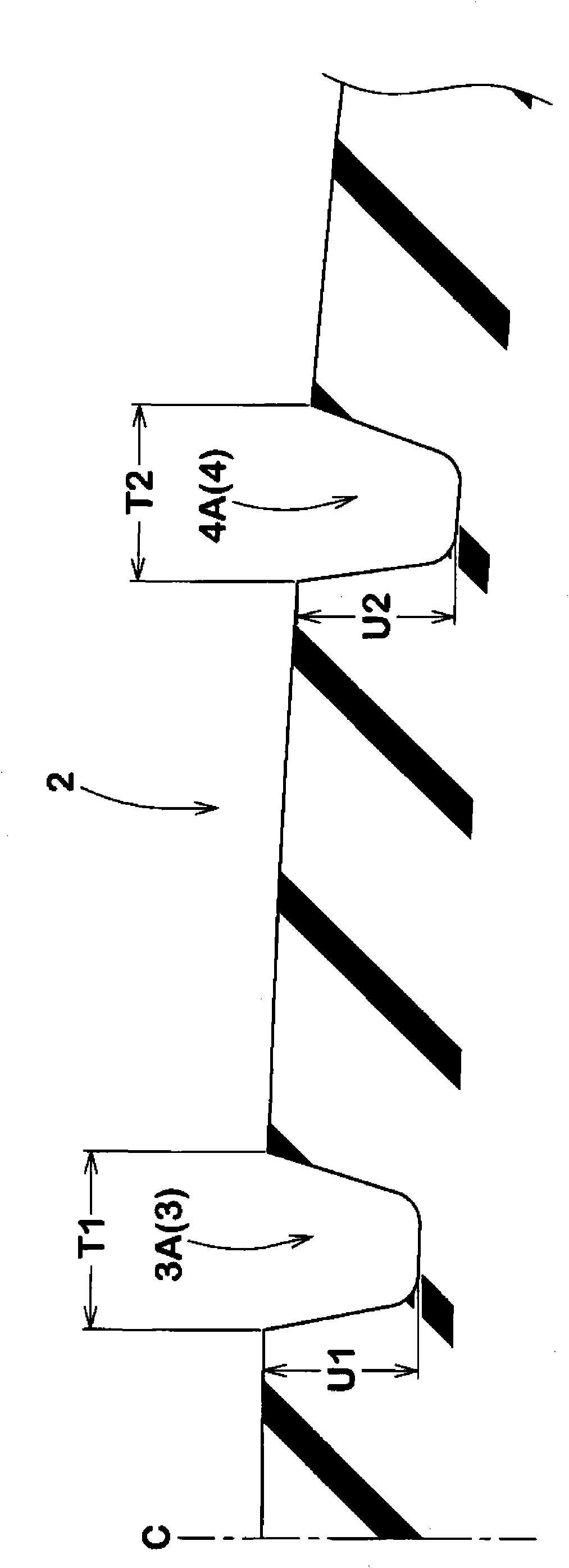
[0072] Groove width T1 / TW of crown circumferential groove: 7.5%

[0073] Groove width T2 / TW of shoulder circumferential groove: 6%

[0074] Groove depth U1 of crown circumferential groove: 9.5mm

[0075] Groove depth U2 of the middle circumferential groove: 9.5mm

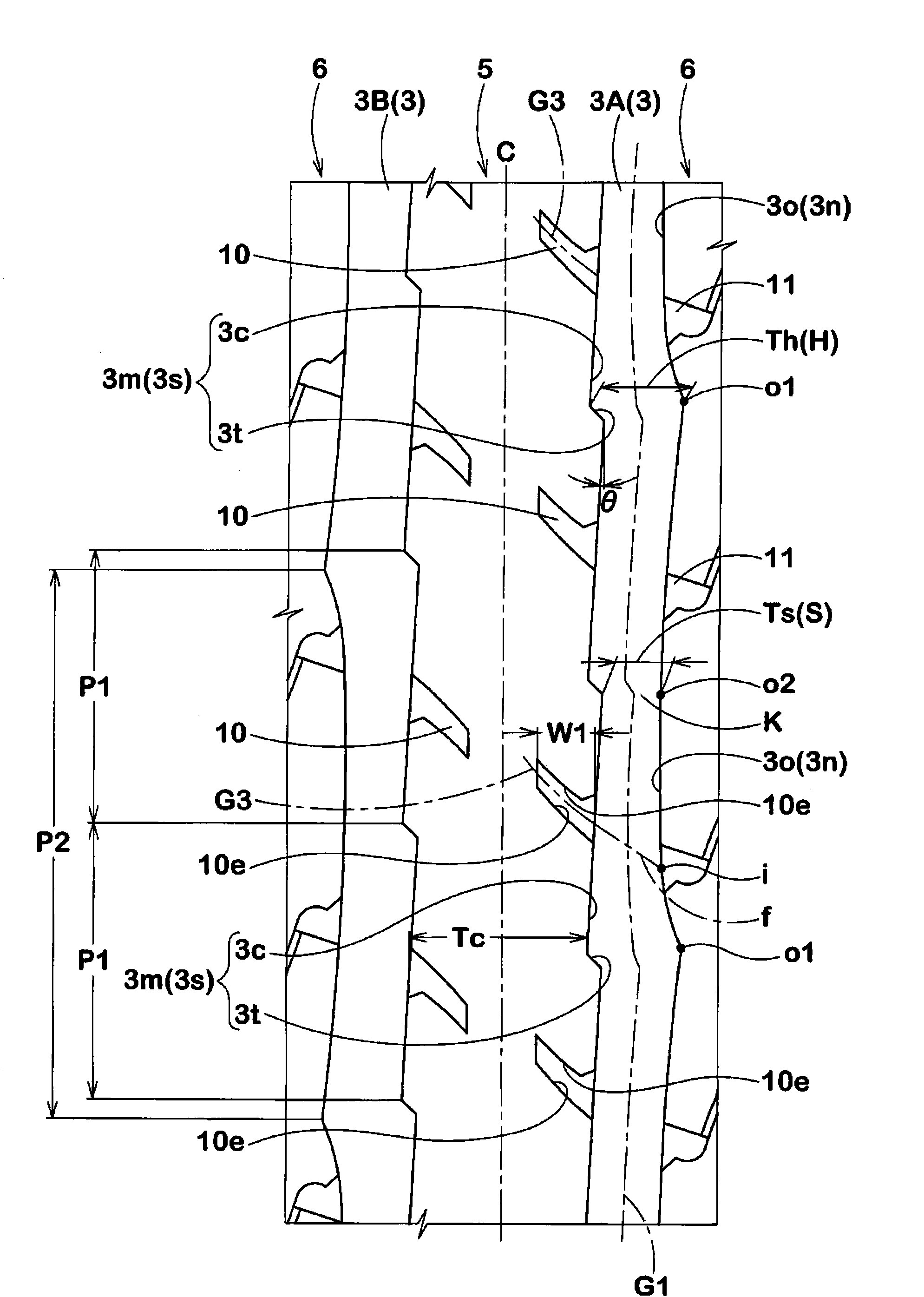
[0076] The ratio c / R of the tire axial distance c between the concave portion o1 and the convex portion o2 and the radius of curvature R: 0.009

[0077] Ratio ...


PUM


Abstract

A pneumatic tire 1 having excellent on-snow performances improved with maintaining steering stability and uneven wear resistance and including tread portion 2 having a pair of crown circumferential grooves 3 which extend continuously in the tire circumferential direction on both sides of tire equator C and have groove edges, one edge 3m extending in such a zigzag form that italic L-shaped groove edge segments 3s are continuously connected to each other in the circumferential direction, and the other edge 3n extending in such a wavy form that circular arc groove edge segments 3o each having a circular arc shape convex toward a groove center are continuously connected to each other in the circumferential direction, wherein each of the italic L-shaped groove edge segments 3s comprises long side part 3c inclined at an angle of 1 to 20 DEG with respect to the circumferential direction, and short side part 3t having a circumferential length smaller than that of the long side part 3c and inclined in the opposite direction to the long side part 3c with respect to the circumferential direction.

Description

technical field [0001] The present invention relates to a pneumatic tire that maintains handling stability and uneven wear resistance and improves on-snow performance. Background technique [0002] Conventionally, in order to improve running performance on snowy roads, it is known to increase the snow column shearing effect by bending the main groove extending in the tire circumferential direction. Also, for the purpose of improving steering stability on icy roads, it is known to form a plurality of sipes on a block or the like to increase edge components. [0003] However, a plurality of sipes or full-open sipes with both ends connected to the main groove, etc., have the problem of lowering the rigidity of the block, deteriorating the steering stability on a dry road surface, and causing uneven wear. The related art is as follows. [0004] Patent Document 1: Japanese Patent Laid-Open No. 2003-072321. Contents of the invention [0005] The present invention is made in v...

Claims


Application Information

Patent Timeline
Patent Type & Authority Applications(China)
IPC IPC(8): B60C11/04B60C11/11
CPCB60C2011/0383B60C2011/0388B60C11/0309B60C11/0306
Inventor 羽田圭宽
Owner SUMITOMO RUBBER IND LTD
Learn More