Cleanroom system and cleanroom air-conditioning method

An air conditioning, clean room technology, applied in air conditioning systems, space heating and ventilation details, heating and ventilation control systems, etc., can solve the problems of high cost, high energy consumption, heavy workload of the cooling device 16, etc., to reduce Work load, high humidification efficiency, cost reduction effect

Inactive Publication Date: 2010-12-22
AU OPTRONICS CORP
View PDF0 Cites 8 Cited by
  • Summary
  • Abstract
  • Description
  • Claims
  • Application Information

AI Technical Summary

Problems solved by technology

[0009] However, in the above-mentioned clean room system 10, the temperature adjustment device 143 includes two coils 145, 146, so the temperature adjustment device 143 has many components and the cost is relatively high.
In addition, the water-washing humidifier 144, the first coil 145 and the second coil 146 are arranged in the air-conditioning room 142, so the volume of the air-conditioning device 14 is relatively large.
In addition, the second airflow S2 completely passes through the cooling device 16 to achieve cooling, and the cooling device 16 has a heavy workload and consumes a lot of energy.

Method used


Image

  • Cleanroom system and cleanroom air-conditioning method
  • Cleanroom system and cleanroom air-conditioning method
  • Cleanroom system and cleanroom air-conditioning method

Examples


Embodiment Construction

[0048]In order to further explain the technical means and effects of the present invention to achieve the intended purpose of the invention, the specific implementation, structure, and characteristics of the air conditioning system and adjustment method for the clean room proposed according to the present invention will be described below in conjunction with the accompanying drawings and examples. and its efficacy are described in detail below.

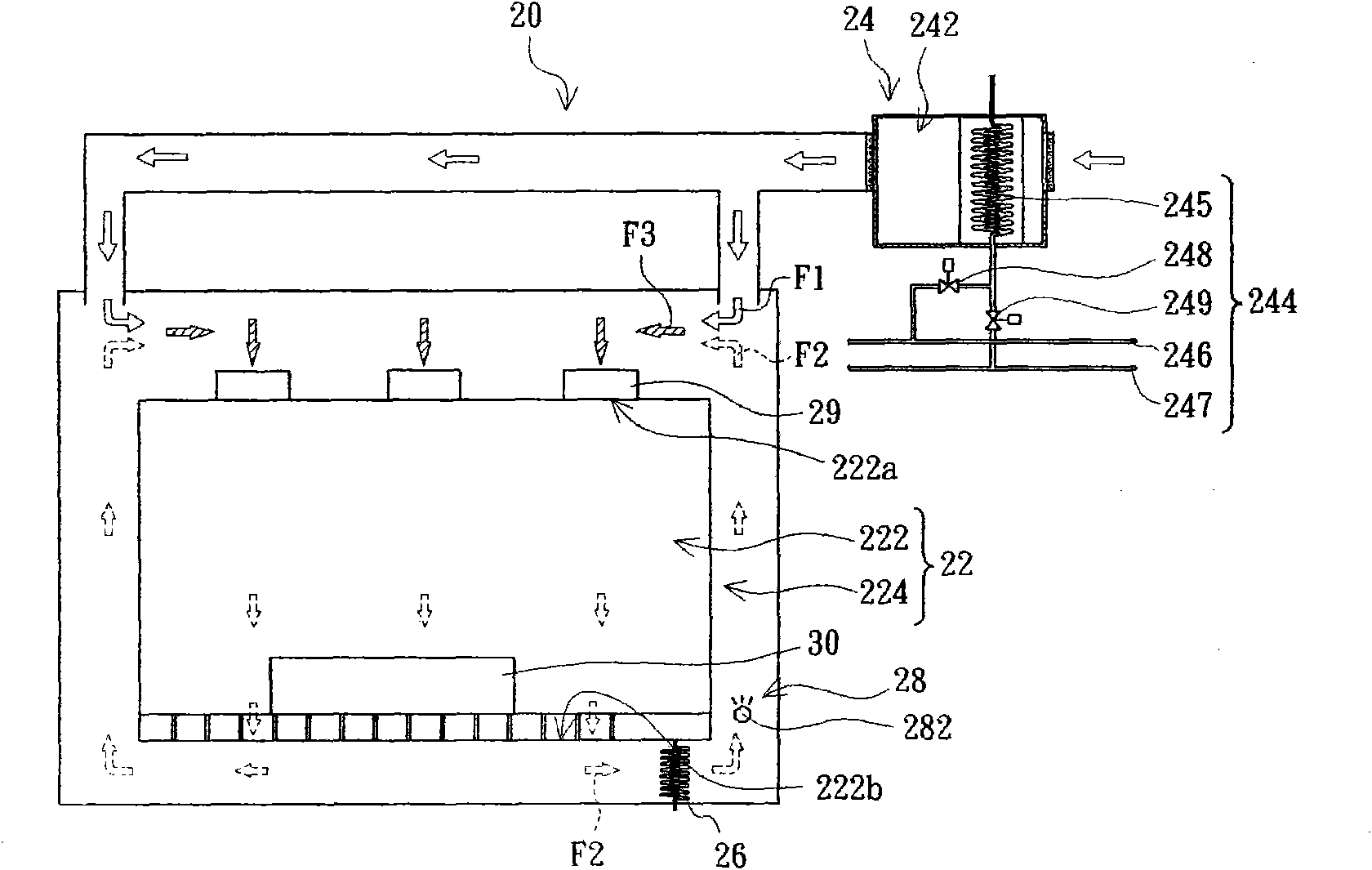
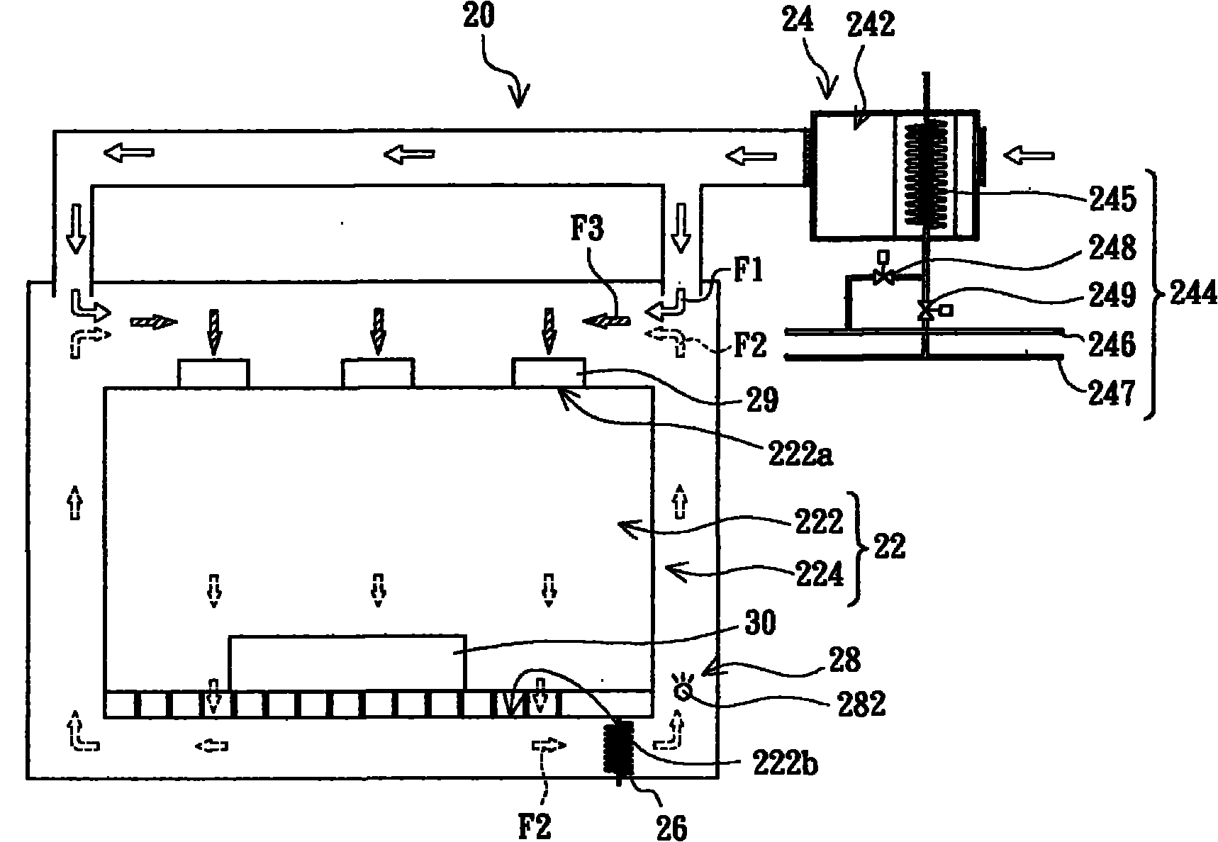
[0049] See figure 2 , The clean room system 20 of the present invention includes a clean room 22 , an air conditioner 24 , a cooling device 26 , a high pressure water mist humidifier 28 and a plurality of fan filter units 29 .

[0050] The clean room 22 includes a clean air room area 222 and a return air area 224 outside the clean air room area 222 . The clean air chamber area 222 has a plurality of air inlets 222a and a plurality of air outlets 222b. The return air area 224 communicates with the clean air chamber area 222 through ...


PUM


Abstract

The invention provides a cleanroom system comprising a cleanroom, a high-pressure water mist humidifier and an air conditioning device, wherein the cleanroom comprises a clean air chamber zone and an air return zone arranged on the periphery of the clean air chamber zone, the clean air chamber zone is provided with an air inlet and an air outlet, and the air return zone is communicated with the clean air chamber zone by the air inlet and the air outlet; and the high-pressure water mist humidifier is arranged in the air return zone. The air conditioning device comprises an air conditioning chamber and a thermostat, wherein the air conditioning chamber is communicated with the air return zone and is suitable to provide first air flow which flows through the inner part of the air conditioning chamber to enter the air return zone; the thermostat is used for regulating the temperature of the first air flow; second air flow enters the air return zone after leaving the clean air chamber zone from the air outlet, is humidified and cooled by the high-pressure water mist humidifier in the air return zone and is combined with the first air flow to form third air flow; and the third air flow enters the clean air chamber zone from the air inlet. In addition, the invention also provides a cleanroom air-conditioning method.

Description

technical field [0001] The present invention relates to a workplace system and a workplace air conditioning method, and in particular to a clean room system and a clean room air conditioning method. Background technique [0002] In industries or laboratories such as semiconductor and electronics factories, product production or test equipment is generally installed in a clean room, so that the product or test results will not be affected by impurities or dust in the air. Therefore, the environment inside the clean room must be strictly controlled, such as temperature and humidity must be maintained within a certain range. [0003] See figure 1 , an existing clean room system 10 includes a clean room 12 , an air conditioner 14 , a cooling device 16 and a plurality of fan filter units 18 . The clean room 12 includes a clean air room area 122 and a return air area 124 located around the clean air room area 122 . The clean air chamber area 122 has a plurality of air inlets 12...

Claims


Application Information

Patent Timeline
Patent Type & Authority Applications(China)
IPC IPC(8): F24F3/16F24F3/14F24F13/30F24F11/02
Inventor 林志宏翁育群陈炳义
Owner AU OPTRONICS CORP
Why Eureka
Try Eureka